Introduction
Product Identification
Safety
Operating
Replacement Parts
Service Intervals
Service Lubrication
Service Engine - Models 325 and 335
Service Engine - Model 345
Service Transmission
Service Steering & Brakes
Service Mower
Service Electrical
Service Miscellaneous
Troubleshooting
Storage
Assembly
Install Steering Wheel and Tilt Lever
Installing Plastic Front Bumper Cover
Position Mower Wheels (48C Mowers)
Position Mower Wheels (54-Inch Mower)
Plastic Discharge Chute (48C and 54 Mowers)
Specifications
Warranty
John Deere Quality Statement
Service Record
CopyrightŠ Deere & Company

Assembly
Remove Tractor from Crate
1. Remove unit from metal shipping crate. Remove all protective wrap from hood.
2. Remove protective shipping plastic wrap from the leaping deer emblem between the headlights.
3. Model 345: Open hood and remove protective wrap from the radiator cap.
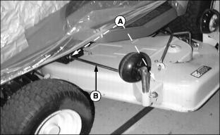
4. 54 Mower: Remove two quick pull pins (A) and deck support rod (B) from left hand side of deck. Discard pins and rod.
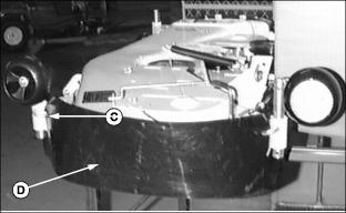
ˇ 54 Mower: Pull out two J-pins (C) to remove and recycle plastic deck cover (D).
Install Steering Wheel and Tilt Lever
1. Turn front wheels until they are pointing straight forward.
2. Remove and discard white plastic cap from steering wheel shaft.
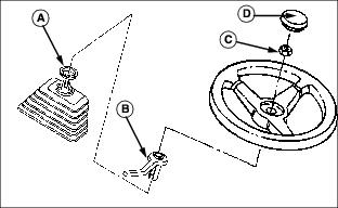
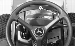
3. Install plastic spacer (A) on shaft.
4. Install lever (B) on shaft.
5. Install steering wheel on shaft.
6. Install and tighten nut (C) to 20 Nˇm (15 lb-ft).
7. Install leaping deer cap (D).
Installing Plastic Front Bumper Cover
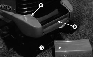
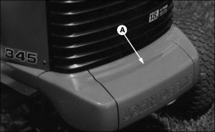
1. Pick up and slide front bumper cover (A) over weight bracket (B) and tip up and slide it into slots (C).
2. Push down on front center of front bumper cover (A) until it snaps in place over weight bracket.
Position Mower Wheels (48C Mowers)
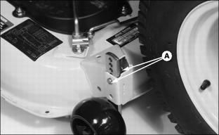
1. Pull out spring pin and pin (A). Remove gage wheel from shipping position and install as shown.
2. Move mower wheels up or down until wheels are approximately 6-13 mm (1/4-1/2 in.) above mowing surface and install pin and spring pin (A).
3. Adjust all wheels to the same height, or if applicable, adjust rear wheels to roll on the ground:
ˇ To adjust wheel by 13 mm (1/2 in.) increment, move wheel up or down one hole.
ˇ Install spring pin and pin to LOCK wheels in position.
Position Mower Wheels (54-Inch Mower)
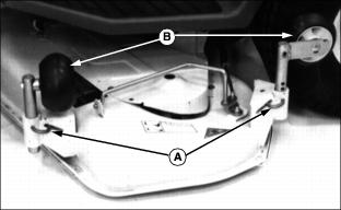
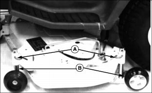
1. Pull out on J-pins (A) and remove mower wheel assemblies (B) from brackets.
2. Hoist rear of tractor to install wheel assemblies.
3. Install wheel assemblies (B) in brackets and release J-pins (A) to lock wheels in place.
4. Remove hoist from rear of tractor.
5. Check mower level. (See Leveling Mower (Front-To-Rear), Leveling Mower (Side-To-Side) and Adjusting Mower Wheels as described in the OPERATING THE MOWER section.)
Break-In Electric PTO Clutch
1. Start engine and push throttle lever up to full throttle position.
ˇ ENGAGE PTO by pulling handle (A) up and allow mower to run for 10 seconds.
ˇ DISENGAGE PTO by pushing handle (A) down and wait 10 seconds.
3. Repeat Step 2 for 12-15 cycles. PTO clutch is now properly burnished.
Plastic Discharge Chute (48C and 54 Mowers)
NOTE: Plastic discharge chute and attaching hardware is found in the bag of parts.
1. Install discharge chute to mower deck with two M8 x 16 bolts (A) and lock nuts (B).
2. Tighten nuts to 20 Nˇm (15 lb-ft).
Connect and Check Battery
Battery is filled with acid and charged when it left the factory. To extend battery life, charge the battery prior to delivery.
1. Check battery voltage. Battery should be charged if voltage is below 12.3 volts. Battery is fully charged at 12.6 volts. (See Charging the Battery in the SERVICE-ELECTRICAL section.)
NOTE: Do not remove the BLACK negative (-) protective cap at this time.
2. Remove and discard the RED positive (+) protective cap from the positive (+) battery terminal.
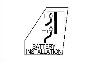
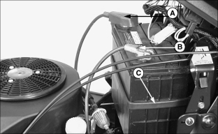
3. Connect red POSITIVE (+) cable (A) to battery. Apply petroleum jelly or silicone spray to terminal to prevent corrosion. Make sure connection is tight. Push red positive cover over positive terminal.
4. Remove and discard the black (-) protective cap from the negative battery terminal.
5. Connect black NEGATIVE (-) cable (B) to battery. Apply petroleum jelly or silicone spray to terminal to prevent corrosion. Make sure connection is tight.
6. Inspect retaining strap (C). Battery must be held securely in place.
Install Seat
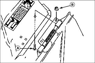
1. Install seat on seat base and install hinge pin (A).
2. Install two E-rings (B) from bag of parts onto hinge pin (A).

