![]()
Introduction
Product Identification
Safety
Operating
Replacement Parts
Service Intervals
Service Lubrication
Service Engine
Service Steering and Brakes
Adjusting Brakes (Automatic Hand Control)
Adjusting Brakes (Automatic Foot Control)
Service Mower
Service Electrical
Service Miscellaneous
Troubleshooting
Storage
Assembly
Specifications
Warranty
John Deere Quality Statement
Service Record

Service Steering and Brakes
Adjusting Brakes (Gear)
1. Park machine safely. (See Parking Safely in the Safety Section.)

· Brake disc (A) is contacting the case (B),
· Brake lever (C) is contacting its mounting bracket (D), top or bottom.
If so, REPLACE friction pucks and brake disc BEFORE making adjustment. (See you Authorized Service Center.)
3. Block the front and rear wheels, and release the parking brake.

4. From the rear of the tractor, locate the brake disc (E), lock nut (F), and friction puck (G).
5. Insert a 0.25 mm (0.010 in.) shim gauge (H) between the disc and friction puck. The shim should slide with slight interference.
· Loosen lock nut (F) until the shim slides in. Tighten the lock nut until the shim has slight interference.
· Remove the shim and cycle the brake pedal. Readjust if needed.
· Install the shim and tighten lock nut (F) until there is slight interference.
· Remove the shim and cycle the brake pedal. Readjust if needed.
Adjusting Brakes (Automatic Hand Control)
1. Park machine safely. (See Parking Safely in the Safety Section.)
2. Unlock the park brake and release brake pedal.
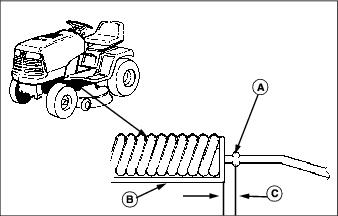
3. Measure distance from inside of brake rod stop tabs (A) to outside of compression spring bracket (B) (located below foot tread area on left-hand side of transmission). Distance (C) should be 2 - 10 mm (0.08 - 0.40 in).

4. If distance is less than or equal to 2 mm (0.08 in):
· Gradually adjust jam nuts (D) until specified measurement is obtained.
· Depress brake pedal and LOCK park brake.
· Measure the distance between edge of compression spring bracket and front edge of brake rod stop tabs. Gap should have a minimum distance of 2 mm (0.08 in).
· Check brake rod compression spring (E). It should not be completely compressed when park brake is locked. A slight air gap should be visible between the coils when proper adjustment is reached.
· Recycle park brake a few times and measure distances each time until specified measurements are obtained.
· Brake lever (F) travel should not exceed 30° (G). If it does, measure brake components individually.
· Spring bracket to stop tabs (minimum): 2 mm (0.08 in)
· Brake lever travel (maximum): 30°
Adjusting Brakes (Automatic Foot Control)
1. Park machine safely. (See Parking Safely in the Safety Section.)
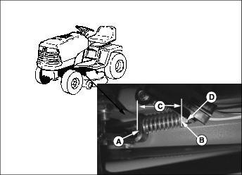
2. Measure distance of the compressed brake spring from bracket (A) to washer (B) (located below foot tread area on left-hand side of transmission). Distance (C) should be 42-43 mm (1.65 - 1.69 in).
If distance (C) is greater than 43 mm (1.69 in) or less than 42 mm (1.65 in), gradually adjust nut (D) until specified measurement is achieved.