![]()
Introduction
Product Identification
Safety
Operating
Replacement Parts
Service Intervals
Service Lubrication
Service Engine
Service Steering and Brakes
Service Mower
Service Electrical
Service Miscellaneous
Troubleshooting
Storage
Assembly
Prepare Mower Deck (42-Inch Only)
Specifications
Warranty
John Deere Quality Statement
Service Record

Assembly
Bag of Parts
Check and Connect the Battery
· Wear eye protection and gloves. · DO NOT allow direct metal contact across battery posts. |
NOTE: The battery was filled with acid and charged when it left the factory. Charge the battery if the mower is not used by the Service Expiration Date indicated on the battery.
Do not attempt to open, add fluid or service battery. Any attempt to do so will void the warranty.
1. Check battery voltage, charge if necessary.
· Battery should be charged if voltage is below 12.3 volts. Battery is fully charged at 12.6 volts.
2. Remove and discard the RED positive (+) protective cap from the positive (+) battery terminal.

3. Pull back the red terminal cover (A) to allow easy access to the positive (+) cable (B) and connect positive (+) cable to battery.
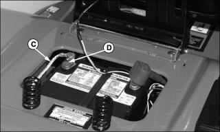
4. Connect silver braided grounding cable (C) to the negative (-) terminal (D).
5. Apply general purpose grease or silicone spray to terminal to help prevent corrosion.
6. Slide red cover over positive battery cable.
Install Seat (Model 2046HS)
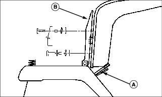
1. Stand seat on mower deck lift handle (A) allowing seat back to rest on steering wheel.
2. Raise seat pan (B) so that it rests against seat bottom.
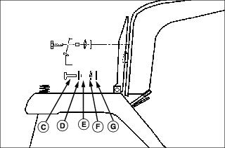
Picture Note: Install hardware in the order shown.
3. Insert capscrew (C) with flat washer (D), spacer (E), spring washer (F) and nylon washer (G) through side of seat pan into seat. Tighten finger tight. Repeat on other side.

Picture Note: Install hardware in the order shown.
4. Insert capscrew (H) into the seat adjustment bracket (I) and then install spacer (J), spring washer (K) and nylon washer (L) onto capscrew and into the seat pan. Tighten finger tight.
5. Pull pin in adjustment bracket assembly and rotate pin to the locked position.
6. Place the remaining capscrew through the seat adjustment bracket and install into seat pan with spacer, spring washer and nylon washer.
7. Tighten all four capscrews.

8. Connect the operator's seat switch connector (M) on to the switch (N) located on the bottom of the seat. Insure the connector locks onto the switch body.
Prepare Mower Deck (42-Inch Only)
· If tractor/mower deck is being set-up for mulching, install mulch cover kit. (See Using Mower Deck Mulch Ready in the Operating Mower section.)
· If tractor/mower deck is being set-up for side discharger or 2-bag bagger DO NOT install mulch cover kit. (See Using Mower Deck Side Discharge OR Using Mower Deck with Optional Equipment in the Operating Mower section.)