![]()
Introduction
Product Identification
Safety
Operating
Replacement Parts
Service Intervals
Service Lubrication
Service Engine
Service Steering and Brakes
Service Mower
Checking for Bent Mower Blades
Servicing Mower Blades (38 and 46-Inch Decks)
Servicing Mower Blades (42-Inch Deck)
Service Electrical
Service Miscellaneous
Troubleshooting
Storage
Assembly
Specifications
Warranty
John Deere Quality Statement
Service Record

Service Mower
Removing Mower
1. Park machine safely. (See Parking Safely in Safety Section.) Disengage mower blades and wait for all moving parts to stop.
2. Put lift lever in highest position.
3. Put wood blocks under each side of mower.
4. Put lift lever in lowest position, bringing deck down onto blocks.
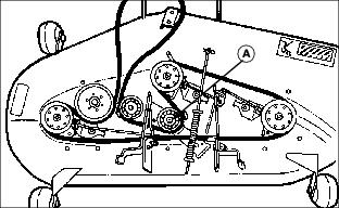
Picture Note: Shown from behind L.H. front wheel.
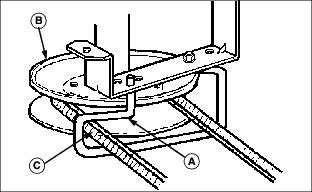
5. Remove belt from engine drive sheave and belt guides:
a. Pull down on left-hand side of belt guide (A) and rotate away from engine pulley (B).
b. Remove belt (C) from belt guide and pulley.
c. Return guide to original position. Insure that the guide is seated into the hole.
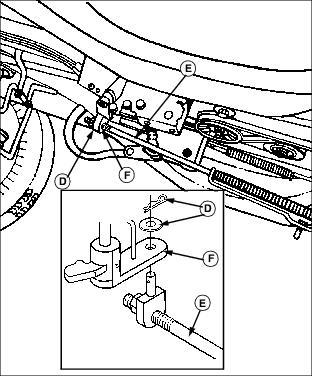
6. Remove spring locking pin and washer (D) holding tension rod (E) to blade drive arm (F).
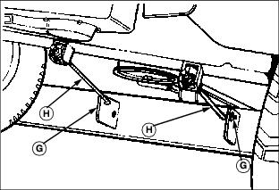
7. Remove spring locking pins and washers (G) from front draft rods (H) and remove draft arms from front axle brackets. Store draft arms with mower.

8. Remove spring locking pins and rear draft pins (I), one on each side, from rear draft brackets (J).
Hold lift lever tightly when releasing from lock (lower) position. |
9. Move lift lever to the highest position.
10. Slide mower out from under the tractor.
Installing Mower
1. Park machine safely. (See Parking Safely in Safety Section.)
2. Put lift lever in highest position.
Hold lift lever tightly when releasing from lock (lower) position. |
4. Put lift lever in lowest position.
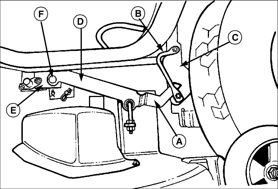
Picture Note: Left side of tractor shown.
5. Position the deck so the rear draft arms (A) are between the guide rods (B) and the lift arms (C).
6. Lift the mower deck. Place wood blocks under each side of mower deck and align the holes in the front of the rear draft brackets (D) with the holes in the frame bracket (E).
7. Insert rear draft pins (F) through rear draft arms and frame bracket from the outboard side. Secure with spring locking pins.

Picture Note: Front of left hand front wheel shown.
8. Insert angled end of front draft rod assemblies (G) through holes in front axle brackets (H).
NOTE: The draft rod assemblies are inserted from the inside of the mower deck brackets toward the outside of the bracket.
9. Raise front of deck and block. Insert angled end of front draft rods into forward holes on the front brackets (I) of the mower deck.
10. Secure each draft rod with flat washer and spring locking pin (J).
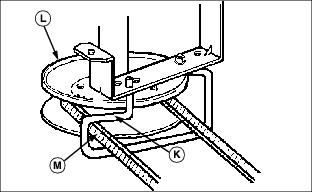
Picture Note: Shown from behind L.H. front wheel.
11. Pull down on left-hand side of belt guide (K) and rotate away from engine pulley (L). Install belt (M) through belt guide and onto pulley. Return guide to original position. Insure that the guide is seated into the hole.
12. Raise tension rod (N) and attach to blade drive arm (O) using flat washer and spring locking pin (P).
13. Raise deck by pressing the lift lever lock and pulling the mower deck lift lever to its highest point.
14. Remove wood blocks from under deck.
15. Check for proper routing and position of all belts.
Replacing Mower Drive Belt
1. Park vehicle safely. (See Parking Safely in Safety Section.) Disengage mower blades and wait for all moving parts to stop.
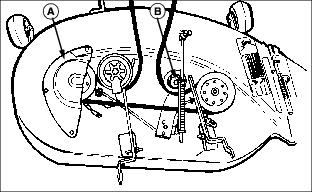
a. Remove three capscrews and belt guard (A).
b. Loosen pulley (B) and move pulley to the right.
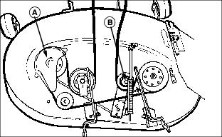
a. Remove two capscrews and belt guard (A).
b. Loosen pulley (B) and move pulley to the right.
a. Remove six capscrews and left and right belt guards.
b. Pull pulley (A) to the left and remove mower drive belt from engine pulley.
4. Inspect belt for wear or damage; replace as necessary.
5. Install belt in reverse order of removal.
6. Reinstall belt guard(s) and tighten capscrews securely.
7. Install mower deck and adjust mower belt tension, if necessary.
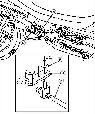
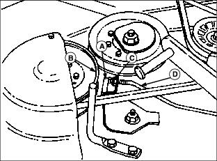
Adjusting Mower Belt Tension
IMPORTANT: Avoid damage! Spindle brake engagement must be checked every time the mower belt tension is adjusted or belt damage may occur. |
1. Park machine safely. (See Parking Safely in the Safety Section.)
2. Place mower deck in lowest setting.

4. Measure distance from bracket (A) to washer (B) on tension rod (C).
· Distance (D) should be: 20 - 25 mm (0.78 - 0.98 in).
5. Continue with the following steps, if adjustment is required.
7. Remove spring locking pin and washer (E) and disconnect tension rod from blade drive arm.
9. Turn fitting on tension rod clockwise to shorten and counterclockwise to lengthen effective rod length.
10. Tighten lock nut (F) to 27 N·m (20 lb-ft.).
11. Assemble tension rod and recheck dimension (D).
12. Check spindle brake clearance.
Adjusting Spindle Brake
1. Park machine safely. (See Parking Safely in the Safety Section.)
2. Place mower deck in lowest setting.
4. Check mower belt tension and adjust, if necessary.
IMPORTANT: Avoid damage! ALL brakes MUST be adjusted. There are TWO spindle brakes on the 38 and 42-Inch decks, and THREE spindle brakes on the 46-Inch deck. |
6. Measure distance from brake surface (A) to pulley braking surface (B). Brake to Pulley Distance should be: 2 - 3 mm (0.08 - 0.12 in).
7. If adjustment is required, turn nut (C) on end of brake rod (D) in correct direction to set brake at proper distance from pulley.
Checking for Bent Mower Blades
1. Park machine safely. (See Parking Safely in the Safety Section).
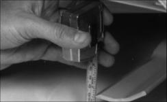
2. Put lift lever in mowing position.
3. Measure distance between blade tip and flat ground surface.
4. Turn blade. Measure distance between other blade tip and flat ground surface.
5. Install new blade, if the difference between the two measurements is more than 3 mm (1/8 in).
Servicing Mower Blades (38 and 46-Inch Decks)
Removing Mower Blades
1. Raise mower deck to gain access to mower blades. If necessary, remove mower deck.
2. Block mower blade with a piece of wood to prevent it from spinning.
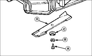
3. Loosen and remove cap screw (A), hardened washer (B), cupped blade washer (C) and blade (D).
4. Inspect blades; sharpen, balance or replace blades as necessary.
Installing Mower Blades
1. Lubricate cap screw threads lightly with a general purpose grease or oil. This lubrication is to prevent rusting and seizing.
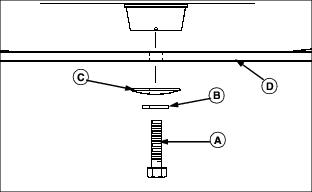
2. Position mower blade (D) with the cutting edge towards the ground onto the mower spindle.
3. Install cupped blade washer (C) with cup side toward the blade.
4. Install hardened washer (B).
5. Install and hand tighten cap screw (A) until mower blade is in full contact (fully seated) with spindle.
6. Block mower blade with a piece of wood to prevent spinning and tighten cap screws to 56 N·m (41 lb-ft).
Servicing Mower Blades (42-Inch Deck)
Removing Mower Blades
1. Raise mower deck to gain access to mower blades. If necessary, remove mower deck.
2. Block mower blade with a piece of wood to prevent it from spinning.
NOTE: Before removing hardware, note the orientation of the cupped blade washer (C) to ensure proper installation.
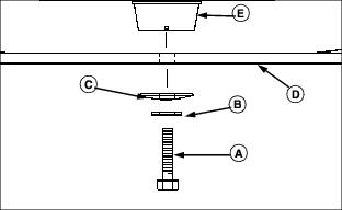
3. Loosen and remove cap screw (A), hardened washer (B), cupped blade washer (C), blade (D) and deflector cup (E).
4. Inspect blades; sharpen, balance or replace blades as necessary.
Installing Mower Blades
1. Lubricate cap screw threads lightly with a general purpose grease or oil. This lubrication is to prevent rusting and seizing.

2. Install deflector cup (E) on spindle.
3. Position mower blade (D) with the cutting edge towards the ground onto the mower spindle.
4. Install cupped blade washer (C) with cup side toward the blade.
5. Install hardened washer (B).
6. Install and hand tighten cap screw (A) until mower blade is in full contact (fully seated) with spindle.
7. Block mower blade with a piece of wood to prevent spinning and tighten cap screws to 56 N·m (41 lb-ft).
Sharpening Blades
Sharpen blades with grinder, hand file, or electric blade sharpener.

Keep original bevel (A) when grinding.
Blade should have 0.40 mm (1/64 in.) cutting edge (B) or less.
Balance blades before installing.
Balancing Blades
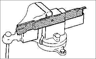
2. Put blade on nail in a vise. Turn blade to horizontal position.
3. Check balance. If blade is not balanced, heavy end of blade will drop.