![]()
Introduction
Product Identification
Safety
Operating
Avoid Damage to Plastic and Painted Surfaces
Adjusting Mower Level (Side-to-Side)
Adjusting Mower Level (Front-to-Rear)
Testing Mower Engagement Lever Switch
Testing Reverse Implement Option (RIO)
Using Travel Controls on Gear Transmission
Using Travel Controls on Automatic Transmission
Using The Reverse Implement Option (RIO)
Using Mower Deck Side Discharge (42-Inch Mower Deck)
Using Mower Deck Mulch Ready (42-Inch Mower Deck)
Using Mower Deck with Optional Equipment (42-Inch Mower Deck)
Unplugging Mower or Optional Bagger
Transporting Machine on Trailer
Avoid Using Ground Engaging Equipment
Replacement Parts
Service Intervals
Service Lubrication
Service Engine
Service Steering and Brakes
Service Mower
Service Electrical
Service Miscellaneous
Troubleshooting
Storage
Assembly
Specifications
Warranty
John Deere Quality Statement
Service Record

Operating
Daily Operating Checklist
o Remove grass and debris from machine.
o Check area below machine for leaks.
Avoid Damage to Plastic and Painted Surfaces
· Do not wipe plastic parts unless rinsed first.
· Insect repellent spray may damage plastic and painted surfaces. Do not spray insect repellent near machine.
· Be careful not to spill fuel on machine. Fuel may damage surface. Wipe up spilled fuel immediately.
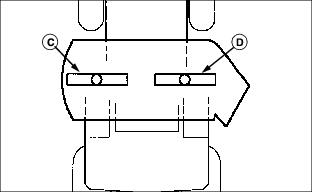
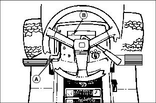
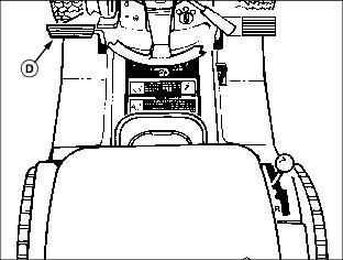
Operator Station Controls
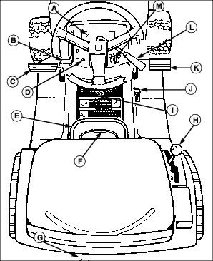
C - Foot Pedal - Brake/Clutch/Return to Neutral
D - Reverse Implement Option Switch
G - Free Wheeling Knob (Automatic Models)
H - Hand Lever: Transmission Shift Lever (Hand Control Units) (or) Cruise Control Lever (Foot Control Units)
J - Foot Pedal, Reverse (Foot Control Units)
K - Foot Pedal, Forward (Foot Control Units)
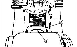
Adjusting Seat
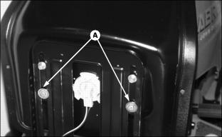
Picture Note: Model with capscrew adjuster used for illustration.
2. Loosen two cap screws (A) two turns.
3. Slide seat forward or rearward on mounting bracket to desired position.
4. Tighten cap screws or knobs.
Using Slide Adjuster (V-Twin Only)
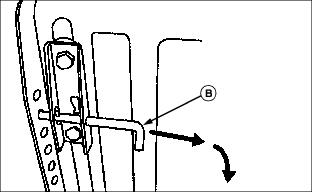
2. Pull pin (B) and rotate pin to the locked position.
3. Slide seat forward or rearward to desired position.
4. Release pin, make sure pin engages in hole in frame.
Adjusting Cutting Height
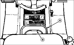
Adjusting Mower Deck Wheels
1. Park machine safely. (See Parking Safely in the Safety Section.)
2. Inflate tires to the correct pressure.
3. Raise lift lever to transport position and adjust cutting height.
4. Move lift lever to mowing position.
NOTE: Bottom of wheels should be approximately 6-13 mm (1/4-1/2 in.) from the ground.

5. Check mower wheel position. Remove bolt (A), bushing (B), washer (C), and nut (D) and move mower wheels to proper hole.
6. Install bolt and tighten with nut to lock wheels in position.
Adjusting Mower Level (Side-to-Side)
NOTE: Mower wheels should not contact the ground when leveling the deck.
1. Park machine safely on a level surface. (See Parking Safely in the Safety Section).
2. Inflate tires to the correct pressure.
3. Adjust cutting height to middle position.
4. Put lift lever in mowing position.
NOTE: The difference between blade measurements must not be more than 3 mm (1/8 in).

Picture Note: A convenient leveling gauge (A) is available from your Authorized Service Center.
5. Position mower blades as follows and measure from each outside blade tip (B) to the level surface.
· Turn left blade (C) as shown. Hold drive belt and turn right blade (D) as shown. Take measurement for both blades.
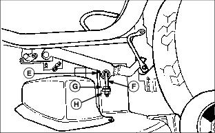
6. Loosen top clamping nut (E) facing inside of mower, on left hand side J-bolt (F), approximately one turn.
7. Loosen upper adjusting nut (G).
8. Adjust lift links by turning lower adjusting nut (H) clockwise to raise left side of mower, counterclockwise to lower left side of mower.
9. Tighten upper adjusting nut.
11. Measure blade tips again and adjust if necessary.
Adjusting Mower Level (Front-to-Rear)
1. Park machine safely on a level surface. (See Parking Safely in the Safety Section).
2. Inflate tires to the correct pressure.
3. Adjust cutting height to middle position.
4. Put lift lever in mowing position.

5. Turn blades so front blade tips (A) point straight forward.
6. Measure from each blade tip to the surface.
· The front blade tip must be 6-9 mm (1/4-3/8 in.) lower than rear blade tip.
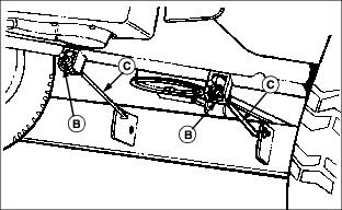
7. Turn nuts (B) on front draft rods (C) equally until adjustment is correct. Turn nut clockwise to raise front of mower deck or counterclockwise to lower front of mower deck.
8. Measure blade tips again and adjust if necessary.
Testing Safety Systems

Use the following checkout procedure to check for normal operation of machine.
If there is a malfunction during one of these procedures, Do not operate machine. See your John Deere dealer for service.
Perform these tests in a clear open area. Keep bystanders away.
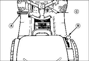
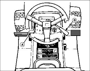
Testing Mower Engagement Lever Switch
3. Push mower engagement lever (A) forward to engage.
Testing Seat Switch
First Test:
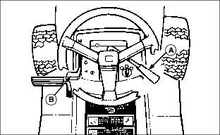
3. Pull mower engagement lever (A) back to disengage.
4. Start engine and move throttle lever (B) to half-speed position.
5. Push mower engagement lever (A) forward to engage.
6. Move throttle lever to fast speed position.
7. Raise up off of seat, but do not get off tractor.
Second Test:

3. Pull mower engagement lever (A) back to disengage.
4. Start engine and move throttle lever (B) to fast speed position.
5. Raise up off of seat, but do not get off tractor.
Testing Park Brake Switch
3. Pull mower engagement lever (A) back to disengage.
Testing Park Brake
1. Shut the engine off and lock the park brake (A).
2. Put transmission in N (neutral).
3. Try to push machine manually. Use free-wheeling lever on units with an automatic transmission.
Testing Reverse Implement Option (RIO)
Before backing up, carefully check the area around the machine. |
3. Look behind the vehicle to be sure there are no bystanders.
4. Begin reverse travel by depressing reverse foot pedal for Automatic transmission or moving gear shift lever to R (reverse) position for Gear transmission.
Using Park Brake
Locking park brake:

1. Push and hold brake pedal (A) down.
2. Move park brake lever (B) forward, then to the left to lock position.
3. Release brake pedal. Pedal should stay down and park brake lever should stay locked.
Unlocking park brake:
1. Push and hold brake pedal down.
2. Move park brake lever to the right, then to the rear.
Starting Engine
NOTE: Engine will not start unless mower is disengaged and transmission is in neutral.
3. Put transmission in neutral.
On Model 2046, move throttle lever (A) to the half-speed position and pull out choke knob (B). Gradually push in the choke knob after the engine starts and warms up.
On all other Models, move throttle lever (A) to the choke position.
On Model 2046, pull out choke knob (B). Push choke knob in as soon as the engine starts.
On all other Models, move throttle lever (A) to the half-speed position.
IMPORTANT: Avoid damage! Starter may be damaged if starter is operated for more than 20 seconds at a time: · Wait two minutes before trying again if engine does not start. |

5. Turn key to start position (C) for no longer than five seconds.
6. Release key to run position (D) when engine starts.
· If engine does not start, wait 10 seconds.
· Turn key to start position again for no longer than 5 seconds.
· Repeat procedure if necessary.
IMPORTANT: Avoid damage! Unnecessary engine idling may cause engine damage. Excessive idling can cause engine overheating, carbon build-up, and poor performance. |
7. Let engine run at half-speed position for a couple of minutes to warm-up before operating machine.
Idling Engine
IMPORTANT: Avoid damage! Unnecessary engine idling may cause engine damage. Excessive idling can cause engine overheating, carbon build-up, and poor performance. |
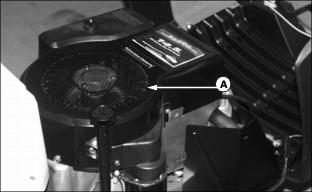
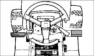
Engine is air cooled and needs a large volume of air to keep cool. Keep air intake screen (A) on top of engine clean.
Stopping Engine
1. Move throttle lever (A) to slow position. Let engine run at low throttle a few seconds.

2. Turn key to stop position (B).
Using Travel Controls on Gear Transmission
IMPORTANT: Avoid damage! Stop machine movement before shifting between reverse and forward to prevent transmission damage. |
To travel forward:

1. Push clutch/brake pedal (A) all the way down to stop machine.
2. Move shift lever (B) to desired travel speed.
3. Release clutch/brake pedal slowly.
To travel in reverse:
1. Push clutch/brake pedal (A) all the way down.
NOTE: The engine and mower will stop as the gear shift lever is moved to R (reverse) if the mower engagement lever is not in the off position.
2. Put mower engagement lever (C) in the off position.
3. Look behind the vehicle to be sure there are no bystanders nearby.
4. Move shift lever (B) to R (reverse) position.
5. Release clutch/brake pedal slowly.
To stop travel:
Using Travel Controls on Automatic Transmission
To travel forward:

· Units with shift lever: Move transmission shift lever (A) to the right and forward to desired speed.
· Units with foot control: Push down the forward travel pedal (B).
To travel in reverse:
NOTE: The engine and mower will stop as the shift lever is moved to R (reverse) or the reverse pedal is pushed if the mower engagement lever is not in the off position.
1. Put mower engagement lever in the off position.
2. Look behind the vehicle to be sure there are no bystanders nearby.
3. Units with shift lever: Move transmission shift lever (A) reward into the R (reverse) position.
Units with foot control: Push down the reverse travel pedal (C).
To stop travel:
· Units with shift lever: Push down on brake/clutch pedal (D). Transmission shift lever will automatically return to NEUTRAL position and brakes will be applied.
· Units with foot control: If cruise control is engaged, move lever to off position. Release travel pedals and unit will automatically return to neutral and stop. Push down on brake/clutch pedal (D). Brakes will be applied to assist in stopping.
Using Cruise Control
Use cruise control when you want to maintain travel speed without having to hold the forward travel pedal down. Cruise control operates only for forward travel.
Engage cruise control:

1. Put the cruise control lever (A) in the off position.
2. Move cruise control lever forward.
· Move cruise control lever toward the position to begin forward travel.
· Increase tractor speed by moving the cruise control lever toward the position.
· Select desired speed and release lever.
Disengage cruise control:
1. Depress brake pedal or put cruise control lever in the off position
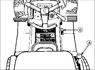
Using The Reverse Implement Option (RIO)
Before backing up, carefully check the area around the machine. |
NOTE: Backing up while the mower is engaged is strongly discouraged. The Reverse Implement Option should be used ONLY when operating another attachment or when the operator deems it necessary to reposition the machine with the mower engaged.
2. Look behind the vehicle to be sure there are no bystanders.
3. Push and hold in the reverse implement switch (A) while depressing reverse foot pedal slightly for Automatic Transmission OR moving the gear shift lever to the R (reverse) position for Gear Transmission.
NOTE: If the engine and mower stop while repositioning the machine, return the mower engagement lever to the off position. Start engine and engage mower. Begin again with Step 2.
4. Release the reverse implement switch and reposition the machine as the machine begins to move rearward.
5. Resume forward travel. The mower should continue operating.
6. Repeat procedure to position the machine again.
Using Mower Lift Lever
1. Push down on lift lever (A) slightly and hold locking lever (B) down with thumb.
2. Move lift lever (A) down to lower mower or up to raise mower.
3. Release locking lever lock (B) to keep lift lever (A) in position.
Using Mower
1. Start engine and allow it to idle for two to three minutes.
2. Lower mower to cutting height.
3. Push throttle lever (A) up to the full throttle position.
4. Push mower engagement lever (B) forward to start mower.
5. Pull lever (B) back to stop mower blades.
Mower Blade Selection
· Standard Blades: Designed for bagging, side discharging, and all mowing conditions.
· Bagging Blades: Designed for cutting and bagging thick, tall grass and/or leaves.
· Mulching Blades: Must be used only with the Mulch Plug. See your John Deere dealer.
Using Mower Deck Side Discharge (42-Inch Mower Deck)
Be careful, sharp edges on mower blades. Always wear gloves when handling mower blades. |
NOTE: For maximum side discharge operation, it may be necessary to change the mower blades, see Servicing Mower Blades in the SERVICE MOWER section.
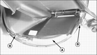
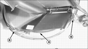
To set-up and operate the 42" deck for side discharge operation the factory installed mulch cover (A) must be removed.
· Lift plastic discharge chute.
· Grasp corner of steel chute, pull outward to unlock and pivot up.
· Unhook both rubber hooks (B) and remove mulch cover.
2. Store mulch cover in a well protected area and have it readily available for when you want to use deck as a mulching deck.
Using Mower Deck Mulch Ready (42-Inch Mower Deck)
Be careful, sharp edges on mower blades. Always wear gloves when handling mower blades. |
NOTE: For maximum mulching operation, it may be necessary to change the mower blades, see Servicing Mower Blades in the SERVICE MOWER section.
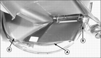
To set-up and operate the 42" deck for mulching operation the factory installed mulch cover (A) must be installed.
· Lift plastic discharge chute.
· Grasp corner of steel chute, pull outward to unlock and pivot up.
· Install mulch cover into deck discharge opening and hook both rubber hooks (B).
Using Mower Deck with Optional Equipment (42-Inch Mower Deck)
Be careful, sharp edges on mower blades. Always wear gloves when handling mower blades. |
NOTE: For maximum mower deck operation, it may be necessary to change the mower blades, see Servicing Mower Blades in the SERVICE MOWER section.
To set-up and operate the 42" deck for either the 2-Bag Bagger or Mulch Plug Kit the factory installed mulch cover (A) must be removed.
· Lift plastic discharge chute.
· Grasp corner of steel chute, pull outward to unlock and pivot up.
· Unhook both rubber hooks (B) and remove mulch cover.
2. Store mulch cover in a well protected area and have it readily available for when you want to use deck as a standard mulching deck.
Pushing Machine
IMPORTANT: Avoid damage! Transmission damage may occur if the machine is moved or towed incorrectly: |
2. Put transmission in N (neutral).

4. Push machine to desired location.
Unplugging Mower or Optional Bagger
· Park the machine safely and lock the park brake before getting off the seat. |
3. Move throttle lever to slow position.
8. Wait for all moving parts to stop.
Transporting Machine on Trailer
Be sure trailer has all the necessary lights and signs required by law.
IMPORTANT: Avoid damage! Transmission damage may occur if the machine is moved or towed incorrectly: |
1. Drive forward onto heavy-duty trailer.
2. Lower mower to trailer deck.
4. Fasten lawn tractor to trailer with heavy-duty straps, chains, or cables. Both front and rear straps must be directed down and outward from tractor.
Avoid Using Ground Engaging Equipment
IMPORTANT: Avoid damage! This tractor is not intended for use with ground engaging equipment. Use of such equipment could result in damage to transmission components. |
This tractor is not intended for use with ground engaging equipment such as a rear tiller, disk, plow or rear mounted scrapper blade.
Using Wheel Weights
· Install front wheel weights for added stability and steering control when you use equipment such as the rear-mounted grass bagger.
· Install rear wheel weights when using the front blade or snowthrower.
· Remove wheel weights when not required.
Using Tire Chains
Tire chains are recommended for use with snowthrower and, under certain conditions, the front blade.
See your Authorized Service Center for Tire Chains.
Mowing Tips
The following recommendations will produce the best lawn cut quality and appearance:
· Keep mower blades sharp. Dull blades will tear grass; tips of grass will then turn brown.
· Cutting grass too short may kill grass and let weeds grow easily.
· Adjust cutting height to remove only 1/3 of the grass at a time.
· Mow grass often. Short grass clippings will decay quickly.
· Mow with engine at full throttle.
· Adjust travel speed to match mowing conditions:
· Travel at SLOW speed when you mow thick, tall grass, make sharp turns or trim around objects.
· Travel at MODERATE speed when you mow thin grass.
· Use a different mowing pattern each time you mow. Overlap mowing paths 50 to 100 mm (2 to 4 in).
· Drive over ridges and through shallow ditches straight-on, not at an angle.
· A thick layer of mulched leave can prevent sunlight from getting to grass and smother it. Taller grass heights allow mulched leaves to dispense easier in lawn. Mulch leaves several times if needed.
· Use a thatcher in late spring or summer to pull up dead grass and aerate ground.