![]()
Introduction
Safety Signs
Preparing Vehicle
Installing
Removing
Operating
Service Safely
Service
Troubleshooting
Storing Machine
Assembly
Identify Drive Assembly Parts (300 Series, 420 and 430)
Identify Drive Assembly Parts (400 and F900 Series)
Installing Discharge Chute Cables
Install Driveshaft (All Models)
Install Locking Pin with Chain
Install Drift Blades (Optional Equipment)
Specifications
John Deere Service Literature
John Deere Quality Statement
Copyright© Deere & Company

Assembly
Remove Snowblower from Crate
1. Remove discharge chute from crate by removing two bolts and washers. Discard this hardware.

The following parts are in the bag of parts:
See your Front Hitch Kit Installation Instructions for assembling the following hardware:
· Large Spring Locking Pin (Used with Front Hitch Kit.)
· Tether Assembly (Used with Front Hitch Kit.)
The above parts are used to restrict the hitch from angling with the snowblower.
Identify Drive Assembly Parts (300 Series, 420 and 430)
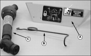
Parts listed below are found in the bag of parts:
Identify Drive Assembly Parts (400 and F900 Series)
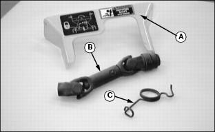
Parts listed below are found in the bag of parts:
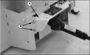
Install Discharge Chute
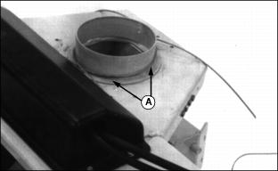
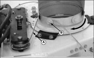
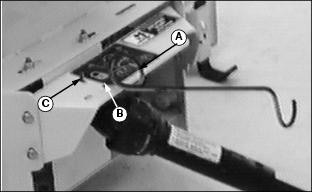
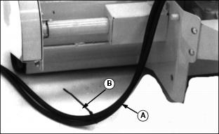
1. Put a light coat of John Deere Moly High Temperature EP Grease or an equivalent onto discharge chute base (A).
2. Lay cables (B) over snowblower shell.
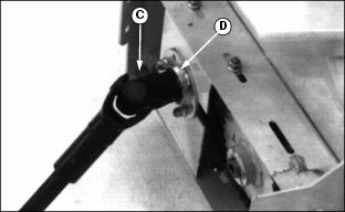
3. Put discharge chute (C) on base. with chute opening facing to the LEFT. You MUST begin with chute facing to the LEFT (as viewed from tractor seat) to get proper rotation of the chute.

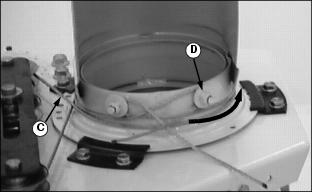
4. Install three large clips (D), and fasten with six self tapping flange hex head bolts (E).
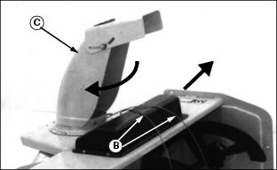
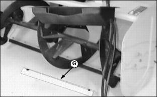
NOTE: When removing the black cable shield (F) an angle bracket (G) will fall from underneath the snowblower. This bracket needs to be installed again when the black cable shield is installed.
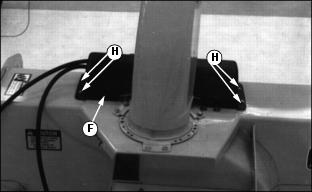
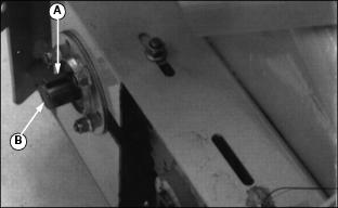
6. Remove black cable shield (F) by removing four bolts (H) and nuts.
NOTE: DO NOT install the black cable shield back on snowblower until after chute installation is complete and you have verified that chute rotation is correct.

7. Slide black cable shield away from pulley's.
8. Check cables to make sure they are still installed on pulleys.
Installing Discharge Chute Cables
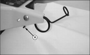
1. Stand behind snowblower. Take left-hand cable (A) and wrap around chute clockwise.
2. Use locking pliers and pull cable tight around threaded stud, and behind lock nut, and washer (B).
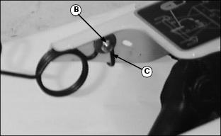
4. Wrap right-hand cable (C) around chute counterclockwise.
5. Use locking pliers and pull cable tight around threaded stud, and behind lock nut, and washer(D).
NOTE: The snowblower needs to be INSTALLED on the Tractor/Front Mower before completing Items 7-9.
If chute does not turn EQUALLY in BOTH directions after assembly, loosen nut, pull cable ends tighter, then tighten nuts.
7. Check for EQUAL turning of chute in BOTH directions.
IMPORTANT: Avoid damage! Make sure you install the long bolts through the black cable shield and bracket. |
8. Tuck excess ends of cables under cable.
9. Install black cable shield and bracket with four bolts and lock nuts.
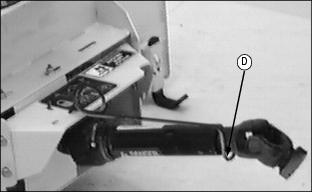
Install Driveshaft (All Models)
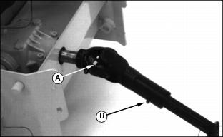
1. Install key (A) in gearbox shaft groove.
2. Apply John Deere NEVER SEEZ® lubricant or an equivalent on sprocket driveshaft (B).
Picture Note: 400 and F900 Series Shown
3. Align groove in driveshaft (C) with key on sprocket shaft (D) and push driveshaft on sprocket shaft.

Picture Note: 400 and F900 Series Shown
4. Align holes on sprocket shaft with holes in driveshaft and install rolled pin (E) through both shafts. Install wire (F) through rolled pin and twist both ends of wire a minimum of three turns.
Lubricate Driveshaft
Lubricate driveshaft grease fittings with John Deere Moly High Temperature EP Grease or an equivalent as shown:
Picture Note: 400 and F900 Series Shown
· 400 and F900 Series: Lubricate two fittings (A) and one fitting (B).

Picture Note: 400 and F900 Series Shown
· 300 Series, 420 and 430: Lubricate two fittings (A).
Lubricate Auger Shaft
· Lubricate grease fittings (A) with John Deere Moly High Temperature EP Grease or an equivalent.
Install Driveshaft Shield

Install PTO Support Rod

· F900 Series: Put end (A) of PTO support rod through square hole on driveshaft shield and fasten with carriage bolt, washer (B), and lock nut (C). Bolt the support rod to the outside of the right-hand side of the shield.
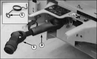

Install Locking Pin with Chain

When installing snowblower on front hitch, make sure front hitch cannot angle by installing locking pin in the front hole (A) on front hitch. Fasten with spring locking pin.
When snowblower is removed from front hitch, put locking pin in storage hole (B). Fasten with spring locking pin.
Install Tie Strap

· 300 Series, 420, 430 and F900 Series: Put a loop (A) in snowblower hydraulic hoses and fasten with black tie strap (B).
· 400 Series: Fasten snowblower hydraulic hoses (A) (without a loop) and fasten with black tie strap (B).
3. Install snowblower on front hitch and check for EQUAL turning of chute in BOTH directions. See Checking Discharge Chute Rotation in the Installing Section.
Install Drift Blades (Optional Equipment)
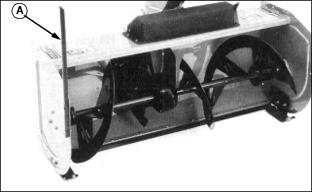
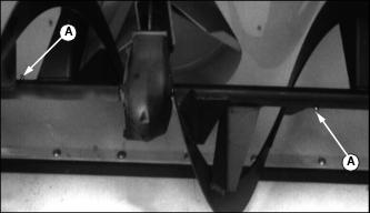
Install drift blade (A) (one on each side of snowblower shell) with two M6 x 20 mm hex head bolts and two M6 lock nuts.