![]()
Introduction
Safety Signs
Preparing Vehicle
Installing
Aligning Snowblower with Front Hitch
Connecting Hydraulic Hoses 400 Series
Checking Discharge Chute Rotation
Checking Hydraulic Hoses and Fluid Level
Removing
Operating
Service Safely
Service
Troubleshooting
Storing Machine
Assembly
Specifications
John Deere Service Literature
John Deere Quality Statement
Copyright© Deere & Company

Installing
Park Vehicle Safely
· Stop vehicle on a level surface, not on a slope.
· Before you leave the operator's seat, wait for engine and all moving parts to STOP.
Avoid High Pressure Fluids

· Hydraulic hoses can fail due to physical damage, kinks, age, and exposure. Check hoses regularly. Replace damaged hoses.
· Escaping fluid under pressure can penetrate the skin causing serious injury. Avoid the hazard by relieving pressure before disconnecting hydraulic or other lines. Tighten all connections before applying pressure.
· Search for leaks with a piece of cardboard. Protect hands and body from high pressure fluids.
· If an accident occurs, see a doctor immediately. Any fluid injected into the skin must be surgically removed within a few hours or gangrene may result. Doctors unfamiliar with this type of injury should reference a knowledgeable medical source. Such information is available from Deere & Company Medical Department in Moline, Illinois, U.S.A.
Parking Tractor/Front Mower
1. Park front of tractor/front mower close to rear of snowblower.
6. Before you leave the operator's seat, wait for engine and all moving parts to stop.
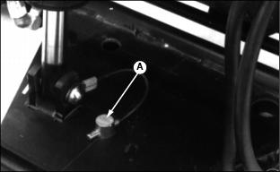
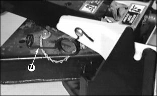
Picture Note: Old Style (400 Series Shown)
7. MAKE SURE lock-out pin assembly (A) is in the front hole on front hitch.

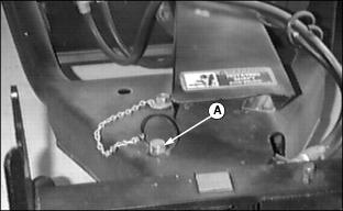
Picture Note: New Style (300 Series, 400 Series, 420, and 430)
Picture Note: New Style (F900 Series)
NOTE: Do not angle snowblower. Driveline damage will occur.
Aligning Snowblower with Front Hitch
IMPORTANT: Avoid damage! To prevent damage to driveline: · Put driveline on PTO rod support (before driving tractor forward). |

NOTE: 400, and F900 Series: Loop of bracket goes inside tractor yoke to control the end piece of driveline.
2. Lower front hitch with lift lever.
NOTE: MAKE SURE lever (E) is in the unlocked position shown.
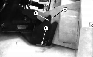
3. Move tractor/front mower forward slowly until slot (F) on front hitch lines up with pin (G) on snowblower.
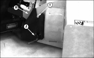
4. Raise front hitch until groove on hitch bracket (H) LOCKS in place under pin (I).
5. Check to be sure that locking pins (J) are ENGAGED into bracket (H) and snowblower.
6. Lower snowblower to the ground.
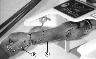
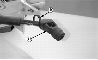
Connecting Driveline


· Install driveline to tractor/front mower PTO shaft (B).
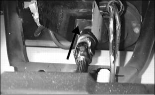
· Push driveline forward until coupler LOCKS in place.
· Install driveline (B) to tractor PTO shaft (C).
· Push driveline to tractor until coupler stops.
· Pull driveline until coupler locks.
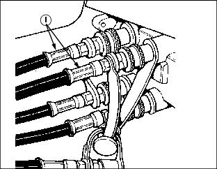
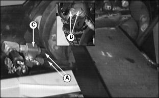
Connecting Hydraulic Hoses 400 Series
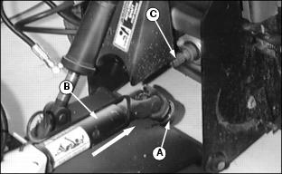
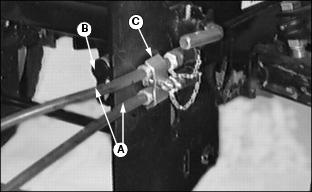
NOTE: For front hitch attachments, the hydraulic cylinder lockout valve (A) must be in the closed position. This locks out the mower and rear implement lift.

1. Locate hydraulic lockout valve (A) under the left foot rest.
2. Turn valve T-handle clockwise until it is bottomed out.

3. Put snowblower hydraulic chute hoses (B) to the inside of bracket (C) on front hitch as shown. (This helps to prevent damage to hoses and possible injury.)
NOTE: If Hydraulic Angling Kit is installed, hose (D) should be to the outside of the bracket and strapped to the lift cylinder hoses as shown.

4. Put hoses through ring (E) on side of tractor.
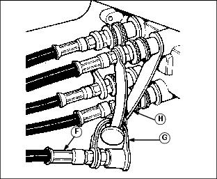
5. If you have installed the "Angling Kit" on your tractor for use with the rotary broom or blade do the following:
· Remove hoses (F) from the top two couplers on tractor. (See decal on tractor platform for reference.)
· Put dust plug cap (G) on hose coupler.
· Put dust plug cap (H) through loop on coupler and connect in plug on snowblower hydraulic hose.
NOTE: To connect hoses to couplers:
· Push and hold tractor coupler sleeve back.
· Put male-end hose fitting into coupler.
· Pull hose to check that hose end is LOCKED in coupler.
· Install each snowblower hydraulic hose (I) to tractor. Match color on hose with decal on tractor platform.
If you have not installed the "Angling Kit" on your tractor:
· Install each snowblower hydraulic hose (I) to tractor. Match color on hose with decal on tractor platform.
Connecting Hydraulic Hoses
300 Series, 420, and 430
NOTE: If Angling Kit is installed for use with broom and/or blade, do Steps 1 and 2.
If Angling Kit is not installed, go to Step 3.
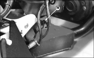
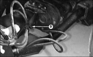
1. Remove hoses (A) from left-hand couplers (B) and clamp to hitch bracket (C).
2. Install dust plugs on couplers.
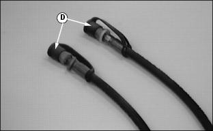
3. Remove dust caps (D) from snowblower hoses.
NOTE: Connecting of hoses is as if operator was seated on seat.
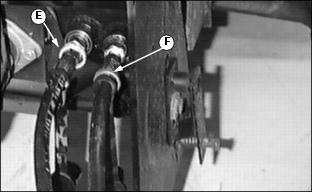
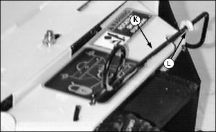
4. Connect (yellow) ring (E) to right coupler on tractor.
5. Connect (silver) ring (F) to left coupler on tractor.
Connecting Hydraulic Hoses
F900 Series
NOTE: If Angling Kit is installed for use with broom and/or blade, do Steps 1 and 2.
If Angling Kit is not installed, go to Step 3.
1. Remove hoses (A) from couplers (B) and pigtail.
2. Slide hoses under gearbox and clamp to hitch bracket (C).
3. Install dust plugs on couplers.
4. Put snowblower hoses through pigtail (D).

5. Remove dust caps (E) from snowblower chute hoses.
NOTE: Connecting of hoses is as if operator was seated on seat.

6. Connect (yellow) ring (F) to RIGHT coupler.
7. Connect (silver) ring (G) to LEFT coupler.
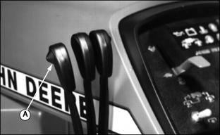
Checking Discharge Chute Rotation
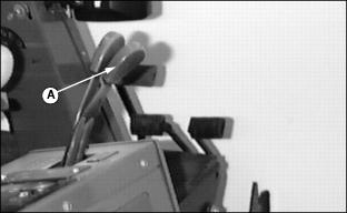
2. Use control lever (A) to turn chute in both directions:
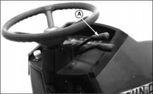
· Pull lever (A) REARWARD to rotate chute to the RIGHT.
NOTE: If chute does not move in the direction indicated, reverse hose location in couplers.
· Push lever FORWARD to rotate chute to the LEFT.
· Pull lever (A) REARWARD to rotate chute to the RIGHT.
NOTE: If chute does not move in the direction indicated, reverse hose location in couplers.
· Push lever FORWARD to rotate chute to the LEFT.

· Pull lever (A) REARWARD to rotate chute to the LEFT.
NOTE: If chute does not move in the direction indicated, reverse hose location in couplers.
· Push lever FORWARD to rotate chute to the RIGHT.
· Pull lever (A) REARWARD to rotate chute to the LEFT.
NOTE: If chute does not move in the direction indicated, reverse hose location in couplers
· Push lever FORWARD to rotate chute to the RIGHT.
IMPORTANT: Avoid damage! MAKE SURE chute is facing to the RIGHT (as viewed from tractor seat) before adjusting cables in order to get proper rotation of the chute. |
3. Chute should turn 90 degrees to each side. If it does not:
Checking Hydraulic Hoses and Fluid Level
Remove transaxle hydraulic fluid dip stick. Check fluid level. If necessary, add fluid. (See your tractor operator's manual for correct procedure.)
· Move hydraulic control levers back and forth and check for leaks.
· MAKE SURE to check for fittings or connections that bind or rub against each other.