![]()
47 and 59-Inch for 55 Series Tractors, 670 and 770 Tractors
Introduction
Safety
Preparing Vehicle
Installing
Removing
Operating
Service Safely
Service
Troubleshooting
Storing Machine
Assembly
Specifications
John Deere Service Literature
John Deere Quality Statement
Copyright© Deere & Company

Assembly
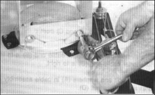
Install Driveshaft
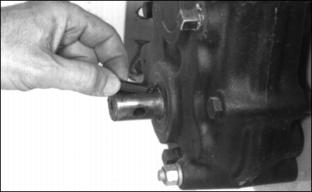
1. Put key in slot of gearbox shaft.
NOTE: NEVER-SEEZ is a trademark of the NEVER-SEEZ Compound Corp.
2. Apply a film of NEVER-SEEZ lubricant on shaft.
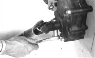
3. Align keyway in driveshaft coupler with key in gearbox shaft.
5. Fasten driveshaft with 5/16 x 2-in. cap screw and stop nut.
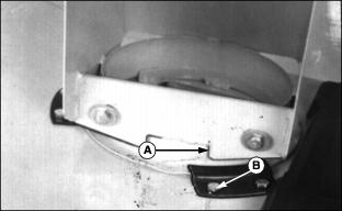
Install Lift Arms
NOTE: Put flat washer under head of cap screw with lock nut to inside.
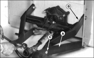
1. Install lower lift arms (A) inbottom hole of snowblower housing with two 1/2 x 1-1/2-in. cap screws, flat washers, and lock nuts.
2. Install upper lift arms (B) in the second hole from the top of snowblower housing with two 1/2 x 1-1/2-in. cap screws, flat washers, and lock nuts.
3. Fasten upper lift arm to lower lift arm with two 1/2 x 1-3/4-in. cap screws (C) and lock nuts.
Install Chute
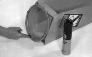
1. Apply John Deere Moly High Temperature EP Grease or equivalent on the bottom and inside flange of discharge chute.
2. Put discharge chute over auger opening.
3. Install three clips with six 5/16 x3/4-in. cap screws, lock washers, and nuts.
5. Turn chute so spout faces left.
6. Turn two 5/16 x 3/4-in. cap screws with flat washers into chute threaded holes two or three turns.
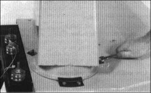
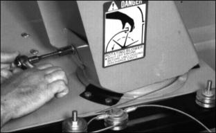
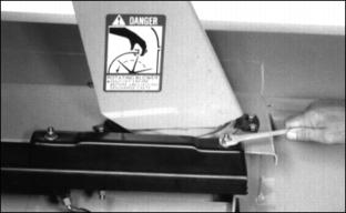
Route Chute Cables
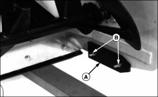
1. Move chute so tab (A) on chute is in line with edge of cap screw (B). Chute opening will be to the left.
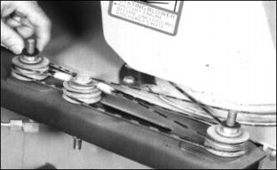
3. Use locking pliers to pull cable tight.
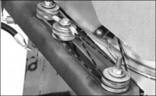
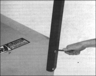
· Around bottom center pulley.
6. Use locking pliers to pull cable tight.
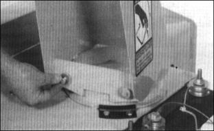
Install Cable Shield
1. Install two flat washers on cable shield bolts.
2. Install cable shield, two washers, and nuts.
Install Drift Blade
Fasten drift blades to auger housing with four 1/4 x 1-in. bolts and four1/4-in. lock nuts.
Install Wear Plate (Optional)
NOTE: Wear plates may be stacked up to three plates on each side. When you install one wear plate use3/8 x 1-in. cap screws. When you install two wear plates use 3/8 x 1-3/8-in. cap screws. When you install three wear plates use 3/8 x 1-5/8-in. cap screws.