![]()
47 and 59-Inch for 55 Series Tractors, 670 and 770 Tractors
Introduction
Safety
Preparing Vehicle
Installing
Removing
Operating
Service Safely
Service
Troubleshooting
Storing Machine
Assembly
Specifications
John Deere Service Literature
John Deere Quality Statement
Copyright© Deere & Company

Installing
Park Vehicle Safely
· Stop vehicle on a level surface, not on a slope.
· Before you leave the operator's seat, wait for engine and all moving parts to STOP.
Avoid High Pressure Fluids
· Hydraulic hoses can fail due to physical damage, kinks, age, and exposure. Check hoses regularly. Replace damaged hoses.
· Escaping fluid under pressure can penetrate the skin causing serious injury. Avoid the hazard by relieving pressure before disconnecting hydraulic or other lines. Tighten all connections before applying pressure.
· Search for leaks with a piece of cardboard. Protect hands and body from high pressure fluids.
· If an accident occurs, see a doctor immediately. Any fluid injected into the skin must be surgically removed within a few hours or gangrene may result. Doctors unfamiliar with this type of injury should reference a knowledgeable medical source. Such information is available from Deere & Company Medical Department in Moline, Illinois, U.S.A.
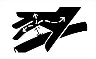
Install Snowblower
1. Put snowblower in front of tractor.
2. Stop tractor engine. Remove key.
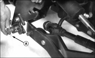
3. Put spring pins (A) in unlocked position so end of pin is against bracket.
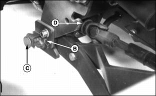
4. Move tractor forward until lugs (B) fit into slots and spring pins (C) snap into place.
5. Check spring pins (C). Pins must be all the way in so snowblower is locked in place.
6. Install coupler (D) on tractor PTO shaft. Push locking collar to rear and pull shaft towards snowblower to be sure coupler locked onto shaft.
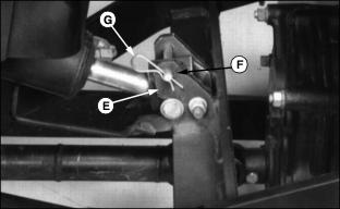
8. Extend lift cylinder until cylinder rod slides into lift bracket (E).
9. Close bracket latch, and fasten it with drilled pin (F) and spring locking pin (G).
10. Stop engine, move hydraulic control levers back and forth to relieve hydraulic pressure.
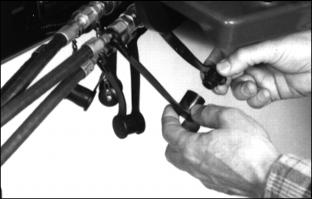
11. Remove dust plugs from couplers (1) and (2). Remove dust caps from hoses.
12. Slide coupler sleeve back on tractor couplers.
13. Put hose fitting into coupler and release sleeve.
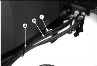
14. Connect hose (H) from cylinder rod end to coupler (1).
15. Connect hose (I) from cylinder head end to coupler (2).
16. Install hoses in hose guide (J).
17. Install coupler dust plugs in hose dust caps.

19. Move SCV lever to all four positions to check for leaks.
21. Check transmission-hydraulic oil level. If necessary, add oil. (See your tractor operator's manual.)

Picture Note: 670 and 770 Tractor
22. Be sure hydraulic hoses are not pinched or contacting other parts.