
Compact Utility Tractor with Hydrostatic Transmission
Introduction
Safety Signs
Controls
Operating Machine
Rotating Blades Are Dangerous - Protect Children And Prevent Accidents
Stay Clear of Rotating Drivelines
Understanding Instrument Panel - Right Side
Understanding Instrument Panel - Left Side
Restarting A Engine That Has Stalled
Restarting A Engine That Has Run Out Of Fuel
Using Power-Take-Off "p" (PTO) - (Operator on Seat)
Using Power-Take-Off "p" (PTO) - (Stationary Operation)
Selecting Front Tire Rolling Direction
Safety Interlock System Checkout Procedure
Avoid Damage to Plastic and Painted Surfaces
Determining Maximum Rear Ballast
Using Optional Rear Cast Iron Wheel Weights
Using Optional Rear Ballast Box
Using Liquid Weight in Rear Tires
Determining Maximum Front Ballast
Using Hydraulic Selective Control Valve (SCV)
Using Mower Deck Lift Controls
Replacement Parts
Service Machine Safely
Service Interval Chart
Service Engine
Service Transmission
Service Electrical
Service Miscellaneous
Troubleshooting
Storing Machine
Assembly
Specifications
Warranty
John Deere Service Literature
John Deere Quality Statement
Copyright© Deere & Company

Operating Machine
Operate Safely
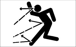
· Check brake action before you operate. Adjust or service brakes as necessary.
· Inspect machine before you operate. Be sure hardware is tight. Repair or replace damaged, badly worn, or missing parts. Be sure guards and shields are in good condition and fastened in place. Make any necessary adjustments before you operate.
· Clear work area of objects that might be thrown. Keep people and pets out of the work area. Stop machine if anyone enters the area.
· If you hit an object, stop the machine and inspect it. Make repairs before you operate. Keep machine and attachments properly maintained and in good working order.
· DO NOT leave machine unattended when it is running.
· Only operate during daylight or with good artificial light.
· Be careful of traffic when operating near or crossing roadways.
· Do not wear radio or music headphones while operating the machine. Safe operation requires your full attention.
Park Safely
· Stop machine on a level surface, not on a slope.
· Before you leave the operator's station, wait for engine and all moving parts to STOP.
Rotating Blades Are Dangerous - Protect Children And Prevent Accidents
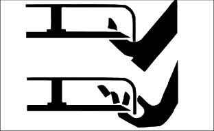
· Never assume that children will remain where you last saw them. Children are attracted to mowing activity, stay alert to the presence of children.
· Keep children in the house when you are operating the machine.
· Turn machine off if a child enters the mowing area.
· Use extra care when you come to blind corners, shrubs, trees, or other objects that may block your vision.
· DO NOT let children or an untrained person operate the machine.
· DO NOT carry or let children ride on machine or any attachment. DO NOT tow children in a cart or trailer.
HELP PREVENT SERIOUS OR FATAL ACCIDENTS:
· Be alert at all times, drive forward carefully. People ESPECIALLY CHILDREN can move quickly into the mowing area before you know it.
· Back carefully. Shut off PTO and look behind the machine carefully, ESPECIALLY FOR CHILDREN, before you back up.
· DO NOT mow in reverse unless it is absolutely necessary.
· Shut off PTO when you are not mowing.
· DO NOT operate machine if you are under the influence of drugs or alcohol.
Use Seat Belt Properly
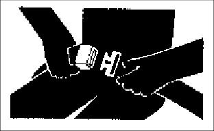
Use a seat belt when you operate with a roll-over protective structure (ROPS) or cab to minimize chance of injury from an accident such as an overturn.
Do not use a seat belt if operating without a ROPS or cab.
Avoid Tipping
· DO NOT drive where machine could slip or tip.
· Stay alert for holes and other hidden hazards in the terrain.
· Slow down before you make a sharp turn or operate on a slope.
· When pulling loads or using heavy equipment, use only approved hitches, limit loads to those you can safely control, and use counterweights or wheel weights when required per this manual or your attachment manual.
· Drive up and down a hill - not across. Be careful when you change direction on a slope.
· DO NOT stop when going up hill or down hill. If machine stops going up hill, STOP PTO and back down slowly.
· DO NOT mow wet grass. Reduced traction could cause sliding.
· DO NOT try to stabilize the machine by putting your foot on the ground.
Operator Training Required
· Study operating section of this manual before operating the machine.
· Operate machine in an open, unobstructed area under the direction of an experienced operator.
· Learn the use of all controls.
· Operator experience is required to learn the moving, stopping, turning and other operating characteristics of the machine.
Keep Riders Off
· Only allow the operator on the machine. Keep riders off.
· Riders on the machine or attachment may be struck by foreign objects or thrown off the machine causing serious injury.
· Riders obstruct the operator's view resulting in the machine being operated in an unsafe manner.
Wear Appropriate Clothing
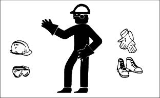
· Wear close fitting clothing and safety equipment appropriate for the job.
· Loud noise can cause impairment or loss of hearing, wear a suitable protective device such as earplugs.
Stay Clear of Rotating Drivelines
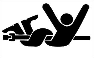
Entanglement in rotating driveline can cause serious injury or death.
· Wear close fitting clothing.
· STOP the engine and be sure PTO driveline is stopped before getting near it.
Check Wheel Bolts
· A serious accident could occur causing serious injury if wheel bolts are not tight.
· Check wheel bolt tightness often during the first 100 hours of operation.
Transport Safely
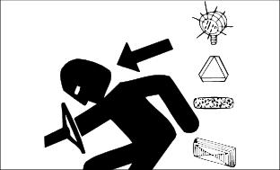
· Use safety lights and devices. Slow moving machines when driven on public roads are hard to see, especially at night. Avoid personal injury or death resulting from a collision with a vehicle.
· Whenever driving on public roads, use flashing warning lights and turn signals according to local regulations. Extra flashing warning lights may need to be installed.
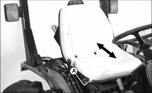
Adjusting Operator Seat
Before starting engine to drive tractor, move seat positioning lever (A) and slide seat forward or rearward to the most comfortable position. Release lever to lock seat in position. Make sure all controls can be reached.
Using Seat Belt
 c CAUTION: Avoid injury! Use a seat belt when you operate with a Roll-Over Protective Structure (ROPS) to minimize chance of injury from an accident, such as an overturn.
|
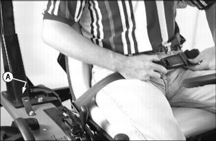
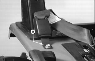
Connect both end of the seat belt until they "CLICK" together. Tighten or loosen seat belt until you are firmly held onto the seat.
To release seat belt, "PRESS" the red button.
When seat belts are not being used, place seat belt ends into each fender mounted retainer (A).
Using Ignition Switch
IMPORTANT: Avoid damage! When tractor is not be used or when tractor is being serviced, make sure key switch is in the "OFF" position and the key is removed. |
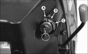
A - "OFF" Position - In this position the engine will not be running.
B - "ON" Position - Move key from "OFF" to this position and the Engine Oil Pressure Light and Battery Charging Light will turn on. You will also hear the engine fuel shut-off solenoid engage with a CLICK.
C - "START" Position - Move key from "ON" to this position and the starter will engage the engine flywheel to start the engine. When the key is released it will automatically return to the "ON" position allowing the engine to run.
Understanding Instrument Panel - Right Side
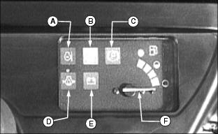
A - Engine Coolant Temperature Light - This light will turn on when the engine coolant is approaching a dangerously hot temperature. If this light turns on, remove load on tractor immediately. Reduce engine to idle speed and check for something blocking air flow to the radiator and check engine coolant level. If light stays on after cleaning grille, STOP engine.
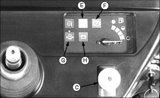
B - PTO Engaged Light - This light will turn on when the PTO is engaged.
C - Parking Brake Set Light - This light will turn on and flash when the Parking Brake is set.
D - Engine Oil Pressure Light - This light will turn on when the ignition key is in the ON position and the engine is not running. If this light turns on while the engine is running, STOP engine. This light will turn on when engine oil pressure is too low. This is an indication that the engine is low on oil.
E - Battery Charging Light - This light will turn on when the ignition key is in the ON position and the engine is not running. If this light turns on while the engine is running, move the throttle lever to the full throttle position. Stop the engine if light remains on. This light will turn on when the alternator output is too low.
F - Fuel Gauge - Show approximately how much fuel is in the fuel tank. Includes Full marker, Half-Full marker and Empty marker.
Understanding Instrument Panel - Left Side
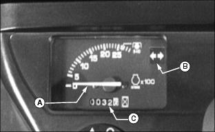
A - Tachometer - Shows engine speed. Engine speed is shown in 100's. Example: If indicator is pointing at 20 (20 x 100 = 2000 RPM). Note the special marker labeled "540 p" - With the indicator pointing at the "540 p" marker, this is the proper engine speed for the 540 RPM Power Take Off (PTO).
· Slow idle speed..................1025 rpm
· Rated speed....................... 2650 rpm
· Fast speed.......................... 2860 rpm
B - Warning Flasher Lights ON Light - This light will turn on and Flash when the Light Switch is turned to the Warning Flasher Lights ON position or Headlights, Taillights and Warning Flasher Lights ON position.
C - Hour Meter - Shows the number of used hours the engine has run at 2650 rpm. If engine has run at less than 2650 rpm, the indicated hours are less than the actual running hours. Use the hour meter as a guide when servicing various components of this tractor.
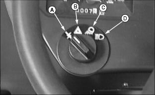
Using Light Switch
NOTE: The light switch will operate only when the ignition key is in the "ON" position.
Rotate switch to the desired position.
C - Headlights and Taillights ON
D - Headlights, Taillights and Warning Flasher Lights ON
Using Throttle
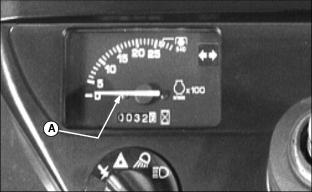
Use the throttle lever (B) to change engine speeds. Use the throttle lever in conjunction with the Tachometer (A) to set engine speeds.
· Slow Idle Speed............................1025 rpm
· Special Marker "540 p"................ 2650 rpm
· Rated Speed............................... 2650 rpm
· Fast Speed................................. 2860 rpm
Using Brakes
|
c CAUTION: Avoid injury! To prevent tipping, do not apply turn brake pedals at high speeds when making a turn; slow down.
|
NOTE: Turn brake pedals can be used for tighter turns. Using turn brake pedals may also avoid unnecessary backing.
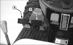
To make a tighter left turn, push down on turn brake pedal (A).
To make a tighter right turn, push down on turn brake pedal (B).
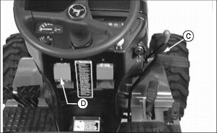
Depress service-park brake pedal (C), then lift up on the park brake lever (D).
Release the service-park brake pedal. The park brake is now set.
Depress service-park brake pedal (C), then push down on park brake lever (D).
Opening Hood
|
c CAUTION: Avoid injury! To prevent injury from moving parts, stop engine and remove ignition key before opening the hood.
|
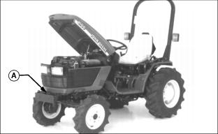
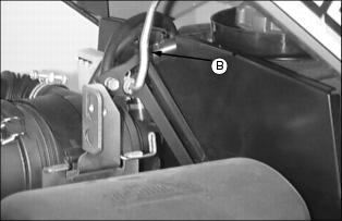
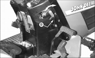
1. Push hood release (A) down to unlock hood.
2. Raise hood and secure with hood support (B).
Removing Front Grille
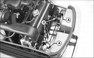
2. Remove two spring locking pins (A).
3. Disconnect wiring harness (B) from both headlights.
4. Lift grille high enough to clear aliment pins (C) and remove grille.
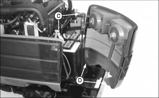
NOTE: The bottom of the grille also has two alignment tabs (D) which set in grooves in the tractor frame.
Using Fuel Shut Off Valve
This engine is equipped with a two position fuel shut off valve.
Open hood and remove service shield from right side of engine.
Locate the fuel filter. The fuel shut off valve is located in the fuel filter body. Rotate fuel shut off valve lever (A) to the "C" or "O" position.
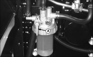
· When performing any type of engine service.
· Fuel shut off valve must be in the full OPEN position for proper fuel delivery to the engine.
Before Starting Engine
|
c CAUTION: Avoid injury! ONLY start engine outdoors or in a well ventilated place. Exhaust fumes are dangerous.
|
1. Observe area under tractor, look for any puddles of hydraulic oil or transmission oil. Maks sure all lubricating fluid levels are at the proper level.
2. Check engine oil level. (See Checking Engine Oil Level in the SERVICE ENGINE section.)
3. Check the fuel tank. Fill fuel tank if necessary.
4. Check fuel shut off valve. Valve must be in the "O" (open) position. See Using Fuel Shut Off Valve in this section.
Starting Engine
|
c CAUTION: Avoid injury! Avoid possible injury or death from machinery runaway.
Do not start engine by shorting across starter terminals. Machine will start in gear if normal circuitry is bypassed. |
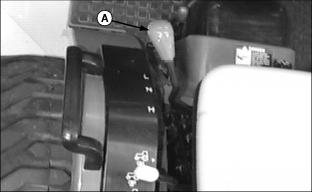
1. Move the 2-Speed Range Lever (A) to the "N" (neutral) position.
2. Move throttle lever (B) forward - 1/2 to 3/4 full throttle.
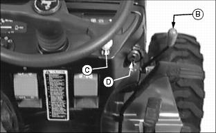
3. Push PTO "p "switch (C) down to the "O" (off) position.
4. Put key in ignition switch (D) and turn to the "ON" position, do not start engine.
NOTE: Steering wheel removed for clarity of photo.
5. Review Instrument Panel (Right Side):
· Engine Oil Pressure Light (G) will be on.
· Battery Charging Light (H) will be on.
· If PTO Engaged Light (E) is on, Push PTO "p" switch down to the "O" (off) position or engine will not start.
· If Parking Brake Set Light (F) is on and flashing, release the parking brake, see Using Brakes in this section.
6. Turn key to the "START" position. As soon as engine starts, release key. The key will return to the "ON" position.
7. After engine starts, check indicator lights:
· Engine Oil Pressure Light should go out within 5 seconds.
· Battery Charging Light should go out within 10 seconds. If indicator does not go out after 10 seconds, set engine speed at full throttle.
· If indicators stay on longer than given time interval, STOP engine, find cause, and correct problem. (See your John Deere dealer.)
Cold Weather Starting Aids
· Install optional engine block heater if you operate tractor in temperatures below -18° C (0° F).
· Install optional hydraulic oil heater if you operate tractor in temperatures below -18° C (0° F).
Warming Up The Engine
IMPORTANT: Avoid damage! In cold weather, run engine a few minutes to allow engine oil and transmission hydraulic oil to warm-up. |
NOTE: Allowing engine to idle for long periods of time will waste fuel and cause a build up of carbon.
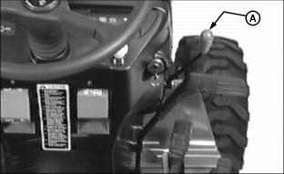
To warm engine, position throttle lever (A) to 1/2 full throttle for 5 minutes without load.
Normal engine operation during warm-up:
· Blue-white exhaust smoke. Amount depends on outside air temperature.
Idling The Engine
NOTE: Allowing engine to idle for long periods of time will waste fuel and cause a build up of carbon.
If you must Idle engine for any length of time:
· Set the parking brake. See Using Brakes in this section
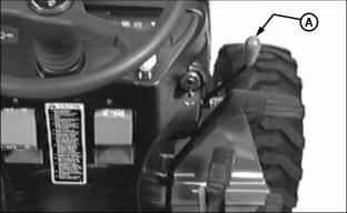
· Pull throttle lever (A) back to set engine speed at 1025 rpm (slow idle speed).
Restarting A Engine That Has Stalled
Should the engine stall when operating under load; restart it immediately to prevent abnormal heat build-up and continue with normal operation or set engine speed at 1025 rpm (slow idle speed) for 1 or 2 minutes before stopping.
Restarting A Engine That Has Run Out Of Fuel
IMPORTANT: Avoid damage! Do not operate starter more than 20 seconds. If engine does not start, wait 2 minutes before you try again or you may damage starter. |
NOTE: Fuel system is self bleeding. Crank engine to allow system to bleed itself.
1. Check fuel tank and fill as required.
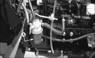
2. Observe fuel filter (A). Make sure fuel shut-off valve on fuel filter is in the "O" (open) position. If necessary, see Using Fuel Shut Off Valve in this section. Fuel is gravity fed into fuel filter, fuel should be visible in the sediment bowl.
3. Start engine. Do not operate starter more than 20 seconds. If engine does not start, wait 2 minutes before you try again or you may damage starter. If necessary, see Starting Engine in this section.
Stopping Engine
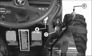
2. Push PTO "p" switch (A) down to the "O" (off) position.
3. Lower all attaching equipment to surface with depth control lever (E) and/or optional SCV lever (D). (See Using 3-Point Hitch or Using Hydraulic Selective Control Valve (SCV) in this section).
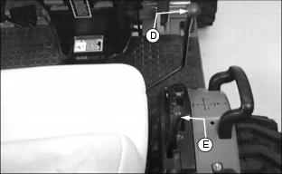
4. Pull throttle lever (B) back to set engine speed at 1025 rpm (slow idle speed).
5. Set the parking brake. See Using Brakes in this section
IMPORTANT: Avoid damage! Do not stop engine immediately after hard or extended operation. Keep engine running at low idle (1500 rpm) for about 2 minutes to prevent heat build-up. |
6. Let engine idle for approximately 2 minutes.
7. Turn key (C) to the "OFF" position.
Operating Transmission
|
c CAUTION: Avoid injury! To avoid injury, before you reverse tractor, look carefully behind it for children.
|
Release the parking brake. See Using Brakes in this section
Set engine speed (A) at 2860 rpm (full throttle). This will be speed the hydrostatic transmission is designed to run at.
NOTE: Both the Forward and Reverse pedals are spring loaded. When you release either pedal, the transmission will automatically return to neutral and the tractor will stop.
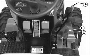
Forward travel: Slowly push down forward pedal (B). Tractor will travel faster the farther down you push the pedal. Release pedal, transmission will return to neutral and tractor will stop.
Reverse travel: Slowly push down reverse pedal (C). Tractor will travel faster the farther down you push the pedal. Release pedal, transmission will return to neutral and tractor will stop.
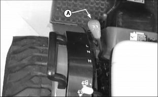
IMPORTANT: Avoid damage! To avoid damaging the transmission, stop the tractor before changing speed range |
The 2-speed range lever is used in conjunction with forward and reverse travel.
"L" - This is low range. In low range the tractor speed is reduced, but tractor power is increased
"N" - This is neutral. In neutral the tractor is in a free-wheeling mode. The Speed Range selector must be in the "N" position when starting the engine. If leaving the tractor unattended - always use the parking brake.
"H" - This is high range. In high range the tractor speed is increased, but tractor power is decreased.
Travel speeds are calculated with a engine speed of 2860 rpm and standard size tires.
· Forward Speed Range: 0 - 7.1 km/h (0 - 4.4 mph)
· Reverse Speed Range: 0 - 7.1 km/h (0 - 4.4 mph)
· Transmission is in neutral - Tractor will free-wheel
· Forward Speed Range: 0 - 16.9 km/h (0 - 10.6 mph)
· Reverse Speed Range: 0 - 8.5 km/h (0 - 5.3 mph)
Using Cruise Control
The cruise control operates only in forward travel.
· Push down forward pedal (A) to the desired travel speed.
· Hold cruise control lever (B) up.
· Remove foot from forward pedal.
· Remove hand from cruise control lever.
· Tap on forward pedal (A) or tap on the service-park brake pedal (C).
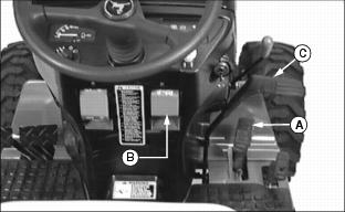
Using Differential Lock
|
c CAUTION: Avoid injury! To prevent tipping, do not attempt to turn on slopes and hills with differential lock engaged.
|
The differential lock is used to provide better traction when rear wheels start to slip. Engaging differential lock will cause both wheels to turn equally.
IMPORTANT: Avoid damage! To prevent damage to differential, do not engage differential lock at high speeds. |
· Push down on differential lock pedal (A). Lock will remain engaged as long as there is rear wheel slippage or pedal is depressed.
NOTE: Turning radius is increased when differential lock is engaged. To assist turning, release differential lock and use turn brake pedals. (See Using Brakes in this section.)
· Remove foot from differential lock pedal. If differential lock will not disengage, depress one turn brake pedal then the other.
Using 4 - Wheel Drive Lever
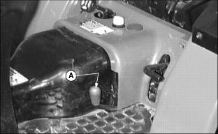
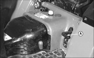
The 4-Wheel Drive Lever (A) enables you to operate your tractor in 4-wheel drive or 2-wheel drive. When the 4-Wheel Drive Lever is engaged the front axle is locked into the powertrain.
|
c CAUTION: Avoid injury! 4-Wheel Drive greatly increases traction, increasing possibility of a tip over while driving on slopes.
|
IMPORTANT: Avoid damage! Always disengage front wheels when driving on a paved surface, or when moving tractor without engine running. For ballast requirements, see your attachment operator's manual. |
· Push 4-Wheel Drive lever (A) forward to engage front wheel drive
NOTE: It may be necessary to reduce load to disengage front wheel drive.
· Pull lever rearward to disengage front wheel drive.
· Maintain front tire pressure at maximum allowable level to insure proper 4-Wheel Drive tire performance in all field conditions.
· Engage 4-Wheel Drive to provide 4-wheel braking.
· Disengage 4-Wheel Drive when transporting tractor to increase front tire life.
· The 4-Wheel Drive can be engaged and disengaged on-the-go and under load.
Using Power-Take-Off "p" (PTO) - (Operator on Seat)
|
c CAUTION: Avoid injury! To avoid injury, make sure all safety shields are installed and being used properly.
|
With operator on seat and engine running, adjust throttle lever until tachometer indicator is pointing at the special marker labeled "540 p" (A).
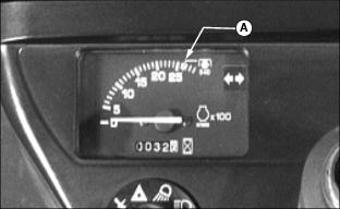
At this point engine speed will be 2650 rpm and PTO speeds will be:
· Rear PTO speed will be 540 rpm
· Mid PTO speed will be 2117 rpm
Use Power Take Off (PTO) Lever (B) to select which PTO you want to use:
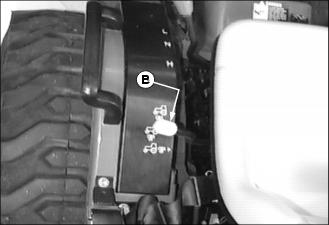
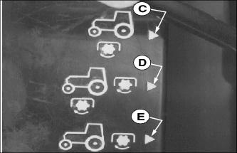
NOTE: If operator leaves the seat after the PTO is engaged the Safety Interlock System will shut down the engine and everything will STOP.
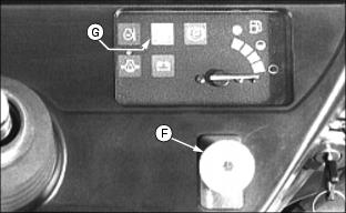
· Pull PTO "p "switch (F) up to the "I" (on) position.
· The PTO Engaged Light (G) will turn on and the selected PTO will be spinning.
Using Power-Take-Off "p" (PTO) - (Stationary Operation)
|
c CAUTION: Avoid injury! To avoid injury:
· Make sure all safety shields are installed and being used properly. · Engage park brake and put 2-speed range lever in "N" (Neutral) position. |
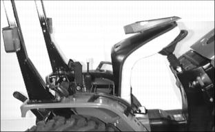
· Set the parking brake. See Using Brakes in this section.
· Move 2-speed range lever into the "N" (Neutral) position. See Operating Transmission in this section.
· Lift seat and place it against the steering wheel.
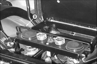
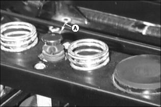
NOTE: Locate seat switch (A). This is a 2 position switch. Pull up on the seat switch plunger for operating the rear PTO without an operator. Push down on the seat switch plunger for normal operation.
· Pull up on the seat switch plunger (A).
· Move seat switch protector (B) to the raised position. The seat can now be lowered and the seat switch plunger cannot be pushed down.
With engine running, adjust throttle lever until tachometer indicator is pointing at the special marker labeled "540 p" (C).
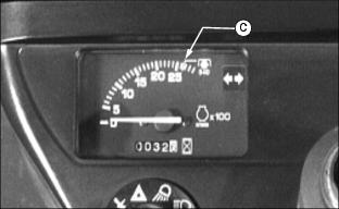
At this point engine speed will be 2650 rpm and PTO speeds will be:
· Rear PTO speed will be 540 rpm
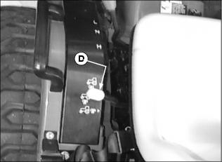
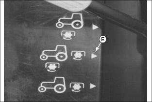
NOTE: When operating the PTO with the tractor in a stationary position only the rear PTO option (E) can be selected.
Use Power Take Off (PTO) Lever (D) to select the rear PTO (E).
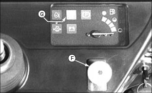
· Pull PTO "p" switch (F) up to the "I" (on) position.
· The PTO Engaged Light (G) will turn on and the rear PTO will be spinning.
Using Drawbar Hitch
|
c CAUTION: Avoid injury! To avoid rearward upset, all towed loads must be attached to the drawbar.
|
IMPORTANT: Avoid damage! Maximum static vertical load on drawbar should not exceed 259 kg (570 lb). Drive slowly with heavy loads. |
Certain heavy equipment such as a loaded single-axle trailer can place excessive strain on the drawbar. Strain is greatly increased by speed and rough ground.
This drawbar is equipped with three adjusting holes for changing the drawbar length. Approximate drawbar lengths:
· Short Drawbar Length - 160 mm (6-1/4 in.)
· Medium Drawbar Length - 260 mm (10-1/4 in.)
· Long Drawbar Length - 355 mm (14 in.)
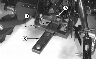
· Remove locking ring (A) and pin (B).
· Adjust drawbar (C) to desired length.
· Install pin and secure with locking ring.
Using 3-Point Hitch
NOTE: The 3-point hitch on this tractor is a Category "1" hitch.
Use depth control lever (A) to raise and lower equipment attached to the 3-point hitch. If equipped with optional mower deck lift kit, the depth control lever will also raise and lower mower deck.
NOTE: The depth control lever has a label showing numbers 1 through 9. These numbers are for reference only. The lower the number, the closer the draft arms will be to the ground.
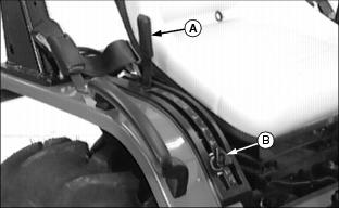
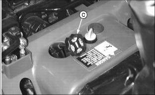
The speed of drop / lock valve (C) is used in conjunction with depth control lever (A). This valve will control how fast a 3-point hitch mounted piece of equipment will drop. This valve will also hydraulically lock the rockshaft (3-point hitch) in a desired position.
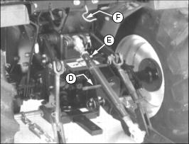
NOTE: When the 3-point hitch is not being used, place center link in the convenient storage hook (F).
Use the center link (D) to level a 3-point hitch implement front-to-rear:
· Lower 3-point hitch implement to surface.
· Rotate center link body (D) to lengthen or shorten the center link. Do not turn body past stops or threads may be damaged.
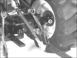
Use the adjustable lift link (G) to level a 3-point hitch implement side-to-side:
· Lower 3-point hitch implement to surface.
· Rotate lift link body (G) to lengthen or shorten lift link until 3-point hitch implement is level side-to-side.
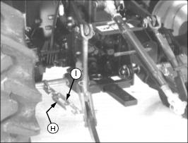
NOTE: Check implement operator's manual for adjusting sway links. When sway links have been properly adjusted, side sway of implement is controlled by position of chains.
Use left and right sway links (H) to adjust 3-point hitch implement side-to-side sway:
· Rotate turnbuckle to lengthen or shorten.
Changing Front Wheel Spacing
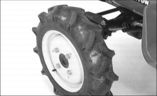
All 4100 Compact Utility Tractors front wheels are in one position. Front wheels should not be installed in the widest position.
Changing Rear Wheel Spacing
See Selecting Tire Tread Width in this section to determine best tread width for your tractor application.
Before you operate tractor on slopes, install rear wheels in the wide position.
2. Put blocks in front and back of front wheels.
3. Set the parking brake. See Using Brakes in this section.
5. Lift wheels off of ground using a safe lifting device. Lift tractor from frame or drawbar support.
6. Remove wheel bolts and tire assembly.
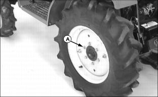
NOTE: If installing directional type tires, position with the tire direction Arrow pointing forward.
· · WIDE POSITION - Install wheel with valve stem to the outside.
2. Install rear wheel bolts (A) and tighten evenly. Tighten rear wheel bolts to 98 N·m (72 lb-ft.).
3. If tractor was equipped with rear wheel weights, reinstall weight and tighten attaching hardware.
Selecting Tire Tread Width
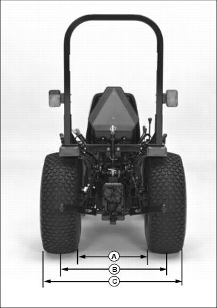
Tractor rear wheel can be changed for different tread widths. Always put rear wheels in wide position when operating on slopes. Refer to one of the following charts to determine tread width for your particular tractor application. See Changing Rear Wheel Spacing in this section.
NOTE: All tread dimensions are for rear wheels only. Front wheels are always in the narrow position and cannot be changed.
Selecting Front Tire Rolling Direction
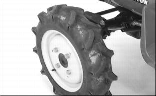
Tractors equipped with directional type tires (such as bar tires) should always be installed with the tire direction Arrow pointing in the direction of pulling travel.
In most cases, the tire direction Arrow will be pointing toward the front of the tractor.
In some cases, the front tires can be installed with the direction Arrow pointing toward the rear of the tractor. This type of tire installation will in some cases improve traction when tractor is equipped with a loader. Because additional traction is needed when backing out of a dirt pile.
Safety Interlock System Checkout Procedure
Use the following checkout procedure to check for normal operation of tractor safety interlock system.
If there is a malfunction during one of these procedures, DO NOT operate machine. (See your John Deere dealer for service.)
Perform these tests in a clear open area. Keep bystanders away.
Test 1 - Operation of Indicator Lights
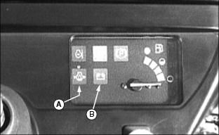
2. Move 2-speed range lever to the "N" position.
3. Push PTO "p" switch down to the "O" (off) position.
|
c CAUTION: Avoid injury! To prevent injury, engine will start if ignition key is turned to the "START" position.
|
4. Turn ignition key to the "ON" position.
· LOOK: Indicator lights (A) and (B) must light.
· LISTEN: The engine fuel shut-off solenoid will engage with a CLICK.
5. If one indicator does not light, see Replacing Instrument Panel Light Bulbs in SERVICE-ELECTRICAL section.
6. If new indicator bulb does not light or no indicators work, see your John Deere dealer.
Test 2 - 2 Speed Range Lever Switch
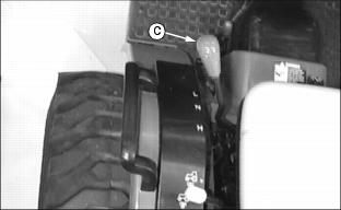
1. Move 2-speed range lever (C) to the "H" position.
2. Turn ignition key to the "START" position. Engine must not start.
Test 3 - PTO Switch
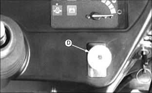
1. Move 2-speed range lever to the "N" position.
2. Pull PTO "p" switch (D) up to the "I" (on) position.
3. Turn ignition key to the "START" position. Engine must not start.
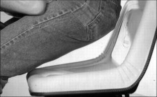
1. Move 2-speed range lever to the "N" position.
2. Start engine. Run engine at 2650 rpm.
3. Pull PTO "p" switch up to the "I" (on) position.
4. Raise up off seat. DO NOT get off tractor.
Engine should begin to die. PTO should immediately SHUT OFF.
5. Turn ignition key to the "OFF" position.
Driving Tractor
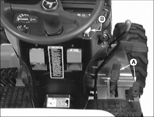
1. Start engine. (See Starting Engine in this section.)
2. Raise 3-point hitch to lift attachment. See Using 3-point Hitch in this section. If tractor is equipped with optional selective control valve. (See Using Hydraulic Selective Control Valve (SCV) in this section).
3. Release the parking brake. See Using Brakes in this section.
NOTE: For light loads such as cutting short grass or operating at transport speeds, use "H" (high range). For heavy loads such as cutting long grass, using a tiller, loader or snowblower, use "L" (low range).
4. Move the 2-speed range lever to the "L" (low range) or "H" (high range) position.
5. Set engine speed at 2650 rpm (rated speed). When you operate an attachment, run engine at the rated speed for best engine and attachment performance.
6. If operating Power-Take-Off (PTO), engage the PTO switch (B). See Using Power-Take-Off "p" (PTO) in this section.
7. Use forward and reverse pedals (A) to move the tractor. See Operating Transmission in this section.
Stopping Tractor
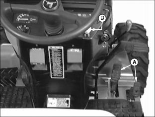
1. Remove foot from forward or reverse travel pedals (A), tractor will stop. Move 2-speed range lever to the "N" (neutral) position. See Operating Transmission in this section.
2. If operating Power-Take-Off (PTO), disengage the PTO switch (B). See Using Power-Take-Off "p" (PTO) in this section.
3. Lower all equipment to the ground. See Using 3-point Hitch in this section.
4. Set the parking brake. See Using Brakes in this section.
5. Stop the engine. See Stopping Engine in this section.
If an accident occurs while operating.
NOTE: If you are using the cruise control, disengage cruise control. See Using Cruise Control in this section.
1. Remove foot from forward or reverse travel pedals (A), tractor will stop. Move 2-speed range lever to the "N" (neutral) position. See Operating Transmission in this section.
2. If possible, set the parking brake. See Using Brakes in this section.
3. If possible, stop the engine. See Stopping Engine in this section.
4. Leave the operator's station. The vehicle's safety interlock system will STOP the PTO and engine when the operator gets off the seat.
Transporting Tractor
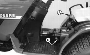
If tractor needs to be pushed or towed a short distance:
NOTE: Tractor is equipped with power steering. Tractor can be steered for a short distance without the engine running.
· Use steering wheel to steer tractor. Steering effort will increase because the engine is not running.
· Move 4-wheel drive lever (B) to the disengaged position.
· Move 2-speed range lever (A) to the "N" (neutral) position.
· If necessary, use the service-park brake pedal to stop tractor.
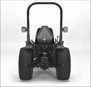
If tractor needs to be driven to another worksite:
· Check fuel supply, if necessary, fill it up.
· This tractor is equipped with a Slow-Moving-Vehicle (SMV) sign, make sure it is intact and clean.
· This tractor is equipped with headlights, taillights and warning flashers, make sure they are all in working order and use them.
· Move 4-wheel drive lever (B) to the disengaged position.
· Move 2-speed range lever (A) to the "H" (high range) position.
· Use the cruise control. See Using Cruise Control in this section.
· If you are transporting tractor with an attachment, check that the attachment is secured and ready for the move.
· Use a heavy-duty trailer to transport your machine.
· Drive machine forward onto a trailer. Lower any attachments to trailer deck.
· Fasten machine to trailer with heavy-duty straps, chains, or cables. Both front and rear straps must be directed down and outward from machine.
· Trailer must have signs and lights required by law.
Avoid Damage to Plastic and Painted Surfaces
· Insect repellent spray may damage plastic and painted surfaces. Do not spray insect repellent near machine.
· Be careful not to spill fuel on machine. Fuel may damage surface. Wipe up spilled fuel immediately.
· Do not wipe dry surface with dry cloth. Plastic and painted surfaces may scratch.
Determining Maximum Rear Ballast
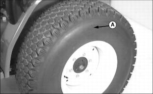
Locate the MAXIMUM LOAD information embossed into the tire side wall (A).
Using Optional Rear Cast Iron Wheel Weights
IMPORTANT: Avoid damage! Do Not exceed maximum weight ratings listed on each tire. See Determining Maximum Rear Ballast in this section. |
1. Mount rear wheels in the wide position for improved stability. See Changing Rear Wheel Spacing in this section.
2. Fasten weight to each rear wheel. A total of three weights per wheel may be used. See your implement operator's manual for installation and required numbers of weights to use.
Rear wheel weights are available from your John Deere Dealer.
Using Optional Rear Ballast Box
IMPORTANT: Avoid damage! Do Not exceed maximum weight ratings listed on each tire. See Determining Maximum Rear Ballast in this section. |
The rear ballast box is used for carrying ballast on the 3-point hitch. Approximate weight of different materials is given in implement operator's manual.
See your implement operator's manual for installation instructions.
Using Liquid Weight in Rear Tires
|
c CAUTION: Avoid injury! Installing liquid ballast requires special equipment and training. Have the job done by your John Deere dealer or a tire service store.
|
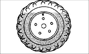
A solution of water and calcium chloride provide safe, economical ballast. Used properly, it will not damage tires, tubes or rims.
Use calcium chloride to prevent water from freezing. A mixture of 0.4 kg of calcium chloride per liter (3.5 lb. per gallon) will not freeze solid above -45° C (-50° F).
NOTE: Use of alcohol as ballast is not recommended. Calcium chloride solution is heavier and more economical.
Fill tubeless tires at least to valve stem level (minimum 75 percent full). Less solution would expose part of rim, possibly causing corrosion. Tube-type tires may be filled to any level below 90 percent.
Determining Maximum Front Ballast
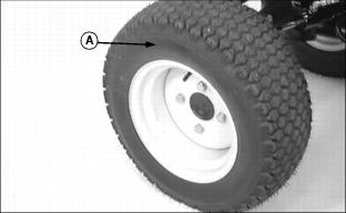
Locate the MAXIMUM LOAD information embossed into the tire side wall (A).
Selecting Front Ballast
|
c CAUTION: Avoid injury! Additional ballast may be needed for transporting heavy integral implements. When implement is raised, drive slowly over rough ground, regardless of how much ballast is used.
|
IMPORTANT: Avoid damage! Do Not exceed maximum weight ratings listed on each tire. See Determining Maximum Front Ballast in this section. |
Add weight to front end if needed for stability. Heavy pulling and heavy rear mounted implements tend to lift front wheels. Add enough ballast to maintain steering control and prevent tip over. Remove weight when it is no longer needed.
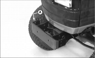
There is a front weight bracket (A) that is an integral part of the tractor frame. This front weight bracket will hold up to five Quick-Tatch weights. Each Quick-Tatch weight is 19 kg (42 lb.).
Quick-Tatch weights and attaching hardware are available at your John Deere dealer.
There is an optional front weight bracket extension kit available at your John Deere dealer. This optional front weight bracket extension kit will then allow you to hold up to nine Quick-Tatch weights.
Using Hydraulic Selective Control Valve (SCV)
This tractor can be equipped with an optional hydraulic SCV and hydraulic outlets to operate attachments equipped with hydraulic cylinders.
The tractor mounted hydraulic outlets are female quick couplers and they are numbered "1, 2, 3, & 4". The female quick couplers are equipped with color coded plastic bands (plugs). There is also a color coded label (A) attached to the engine side panel.
The attachment hydraulic hoses also have color coded bands (plugs). Match color codes hoses to color coded couplers on the tractor.
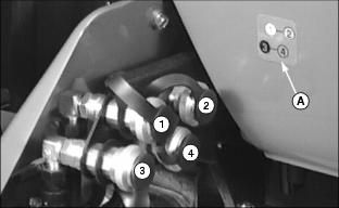
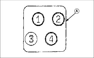
Hoses connected to couplers "1 & 2": Move SCV lever (B) to left to raise attachment or to right to lower attachment. There is also a label (C) to assist you.
Hoses connected to couplers "3 & 4": Move SCV lever (B) forward to lower attachment and rearward to raise attachment.
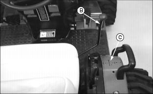
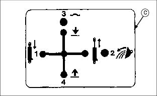
This SCV is also equipped with a "float" position to permit attachments such as blades or loaders to follow ground contours when lowered to operating position. Push lever (B) past valve detent to attain "float" position. Detent can be felt when moving lever forward.
Using Mower Deck Lift Controls
If tractor is equipped with the optional mower deck lift kit, note that there are no special mower deck lift controls. The mower deck lift linkage is all connected to the 3-point hitch. When the 3-point hitch is raised or lowered so is the mower deck lift linkage.
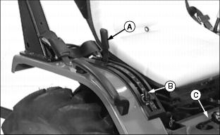
For complete operating instructions of the depth control lever (A), depth stop (B) and the speed of drop / lock valve (C), see Using 3-Point Hitch in this section.