![]()
924DE, 1128DE, 1128DDE and 1332DDE
Introduction
Product Identification
Safety
Operating
Replacement Parts
Service Intervals
Service
Troubleshooting
Storage
Assembly
Bag Of Parts - Models 1128DE, 1128DDE and 1332DDE
Install and Adjust Discharge Chute
Install and Adjust Discharge Chute Crank
Install And Adjust Chute Deflector Cable - Models 1128DE, 1128DDE and 1332DDE
Install And Adjust Traction Drive Cable
Specifications
Warranty
John Deere Quality Statement
Service Record
Copyright© Deere & Company

Assembly
Identify Snowblower Parts
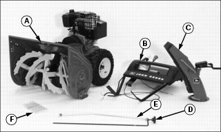
Bag Of Parts - Model 924D
Bag Of Parts - Models 1128DE, 1128DDE and 1332DDE
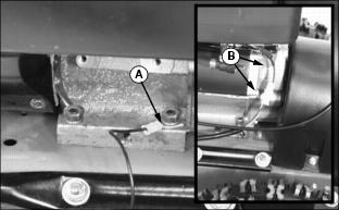
Install and Adjust Discharge Chute
1. Apply a liberal amount of grease to the base of the auger housing and the top of the discharge chute.
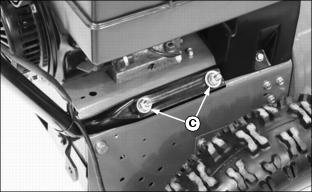
2. Remove 5/16 in. hardware (C) from mounting plate.
3. Install discharge chute (A) to auger housing with chute under chute retainer (B) on auger housing. Install two 5/16 x 5/8 in. round head bolts, two 5/16 in. flat washers and two 5/16 in locknuts. Do not tighten hardware.
4. Adjust discharge chute and attaching bracket until chute is sitting square on the auger housing.
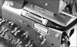
6. Loosen height adjusting hardware (D).
7. Adjust discharge chute until chute is located in the middle of the chute retainer (B).
Install Handle Bars
NOTE: On some units it may be easier to connect the Auger Brake / Drive Cable prior to installing the handle bars.
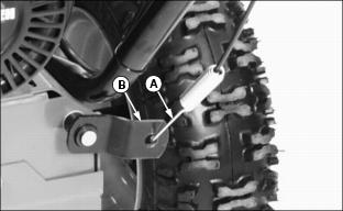
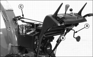
1. Connect the auger brake / drive cable (A) to the auger drive linkage (B).
2. Install handle bar assembly onto blower assembly.
3. On right side of unit, install two 3/8 in. flat washers, 3/8 in. lock washers and 3/8 in. nuts (C) on blower assembly studs. Do not tighten nuts until hardware on left hand side is installed.
4. On left side of unit, install two 3/8 in. flat washers, 3/8 in. lock washers and 3/8 in. hex head bolts (D).
5. Tighten all hardware on handlebar assembly.
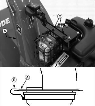
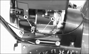
Install and Adjust Discharge Chute Crank
1. Install chute crank (A) through bracket (B), hole in console and into gearbox universal joint (C).
2. Align cross drilled hole in chute crank with cross drilled hole in gearbox universal joint.
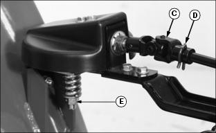
3. Install spring clip pin (D) to retain chute crank.
4. Operate chute crank. Crank should be tight enough so it will not move from engine vibration, but should be loose enough to operate smoothly.
· If chute crank is too loose, tighten nut (E).
· If chute crank is too tight, loosen nut (E).
Install Headlight Wiring
1. Connect ground wire (A) to front engine bolt, between engine block and washer.
2. Connect engine lead to mating connector (B).
Install And Adjust Chute Deflector Cable - Models 1128DE, 1128DDE and 1332DDE
1. Route chute deflector cable (A) through clamp (B).
2. Locate and remove engine shroud bolt (C) on lower right side of engine.
3. Secure clamp with engine shroud bolt. Install and tighten bolt.
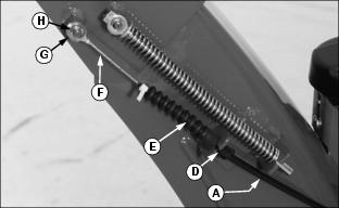
4. Route chute deflector cable (A) along right side of engine and up the left side of the discharge chute.
5. Attach cable to discharge chute with cable clip (D). Make sure rubber boot (E) is pushed down over the cable opening. This will prevent water from entering the cable and freezing.
6. Attach cable end (F) to the chute deflector using a 1/4 in. flat washer (G) and the E-ring (H).
7. Operate chute deflector lever. Lever should be tight enough so it will not move from engine vibration, but it should be loose enough to operate smoothly.
· If lever is too loose, tighten nut (I).
· If lever is too tight, loosen nut (I).
Install And Adjust Traction Drive Cable
Install Cable:
1. Park snowblower on a hard, smooth surface.
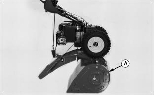
2. Tip machine forward onto housing (A).
3. Put speed selector in first gear.

5. Pull cable (C) tight and install in cable retainer (D).
6. Tighten set screw to retain cable.
Adjust Traction Drive Cable:
1. Disengage the traction drive lever and turn drive wheels by hand.
2. Tighten adjusting nut (E) until wheels begin to drag.
3. Engage and release traction clutch lever to align clutch linkage.
4. Repeat procedure as necessary.
5. When wheel drag is obtained with linkage alignment, loosen adjustment nut (E) a three revolutions. Drive wheels will then turn freely.
Check Clutch / Impeller Brake
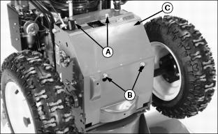
1. Remove two bolts (A) and loosen two bolts (B) to remove access panel (C).
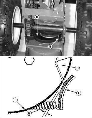
2. Check clearance (G) between brake pad (E) and auger drive belt (F) on auger drive sheave (D):
· With auger drive lever engaged, clearance (G) should be approximately 1.5 mm (1/16 in.).
· With auger drive lever released, the brake pad (E) must contact auger drive belt (F).
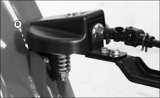
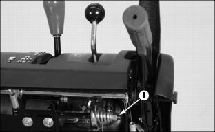
Install And Adjust Shift Rod
IMPORTANT: Avoid damage! To prevent damage to the Friction Disk Wheel, the cotter pin (B) must be installed as shown. This will prevent the open ends of the pin from contacting the rubber disc. |
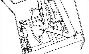
1. Connect shift rod (A) to internal shift linkage (C) and secure with 1/2 in. flat washer (D) and cotter pin (B). Install cotter pin with open ends of pin pointing away from the friction disk wheel. Bend tips of cotter pin.

2. Move shift lever (E) to the "6" (6th gear) position.
3. Remove quick pull pin (H) from upper end of shift rod (A).
4. Push shift rod (A) into housing as far as it will go and hold it in this position until rod adjustment is made.
5. Turn adjusting link (D) until stud aligns with hole in shift linkage (F).
IMPORTANT: Avoid damage! To prevent damage to the Headlight Housing, the quick pull pin (H) must be installed as shown. This will prevent the quick pull pin from contacting the headlight. |
6. Install shift rod adjusting link into shift lever linkage and install quick pull pin (H).
7. Install access panel and hardware.
Add Engine Oil
NOTE: Remind customer to change oil after first two operating hours.
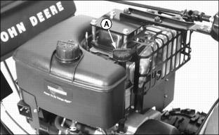
1. Remove "NO OIL" tag and dipstick.
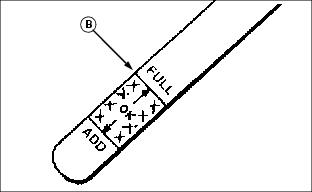
2. Add engine oil through dipstick tube to bring level to the FULL mark (B) on dipstick.
· Approximate capacity for Models 924DE, 1128DE and 1128DDE, 769 mL (26 oz).
· Approximate capacity for Models 1332DDE, 828 mL (28 oz).
3. Install and tighten dipstick.
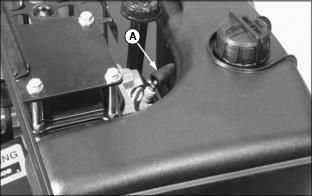
Check Auger Gearbox Oil Level
NOTE: Two different types of gear boxes are used. Both are serviced the same way.
· Fluid level should be at oil fill plug.
Checking Tire Pressure
Tire pressure has been increased for shipping purposes. Check tire pressure with an accurate gauge. Tire pressure should be:
· 924DE, 1128DE and 1128DDE - 138 kPa (20 psi) maximum.
· 1332DDE - 96 kPa (14 psi) maximum.
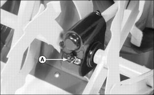
Connect Spark Plug Wire
1. Connect spark plug wire (A).
Extra Auger Drive Shear Bolts
Two extra auger drive shear bolts are included and attached to this unit.
Remind customer to remove extra shear bolts and to store in a safe place.