![]()
924DE, 1128DE, 1128DDE and 1332DDE
Introduction
Product Identification
Safety
Operating
Replacement Parts
Service Intervals
Service
Engine Warranty Maintenance Statement
Cleaning And Gapping Spark Plug
Adjusting Auger Drive Belt Tension
Checking Clutch / Impeller Brake
Adjusting Chute Deflector Lever- Models 1128DE, 1128DDE and 1332DDE
Adjusting Chute Deflector - Model 924DE
Adjusting Traction Drive Clutch
Adjusting Speed / Shift Linkage
Troubleshooting
Storage
Assembly
Specifications
Warranty
John Deere Quality Statement
Service Record
Copyright© Deere & Company

Service
Engine Warranty Maintenance Statement
Maintenance, repair, or replacement of the emission control devices and systems on this engine, which are being done at the customers expense, may be performed by any nonroad engine repair establishment or individual. Warranty repairs must be performed by an authorized John Deere dealer.
Avoid Fumes
Grease
The following greases are preferred:
· John Deere Multi-Purpose SD Polyurea Grease
· John Deere Multi-Purpose HD Lithium Complex Grease
· John Deere Moly High Temperature EP Grease
If not using any of the preferred greases, be sure to use a general all-purpose grease with an NLGI grade No.2 rating.
Wet or high speed conditions may require use of a special-use grease. Contact your Servicing dealer for information.
Engine Oil
Use oil viscosity based on the expected air temperature range during the period between oil changes.
The following John Deere oils are preferred:
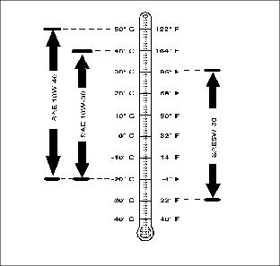
Other oils may be used if above John Deere oils are not available, provided they meet the following specification:
· API Service Classification SG or higher
Gear Oil
Use oil viscosity based on the expected air temperature range during the period between oil changes.
The following John Deere gear case oil is PREFERRED:
The following John Deere gear case oil is also recommended if above preferred oil is not available:
Other gear case oils may be used if above recommended John Deere gear case oils are not available, provided they meet the following specification:
· API Service Classification GL-5.
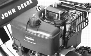
Checking Engine Oil Level
1. Park snowblower on a level surface.
2. Clean area around dipstick.
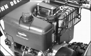
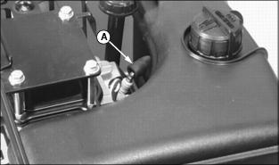
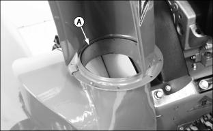
3. Remove dipstick (A). Wipe it off with clean, lint free towel.
4. Install and tighten dipstick. Remove dipstick and locate oil level.
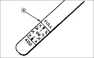
5. Add oil through dipstick tube to bring level to the FULL mark (B) on dipstick.
6. Install and tighten dipstick.
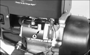
Changing Engine Oil
NOTE: If you do not operate snowblower 25 hours during a season, change oil at end of season.
1. Run engine a few minutes to warm oil. Oil will flow more freely and carry away more contamination when warm.
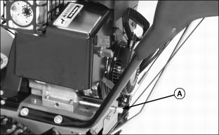
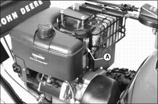
2. Clean area around oil drain plug (A).
3. Position unit so engine oil drain plug is lowest point on engine.
4. Remove dipstick and oil drain plug to drain engine oil.
5. When all oil has drained, install oil drain plug and tighten.
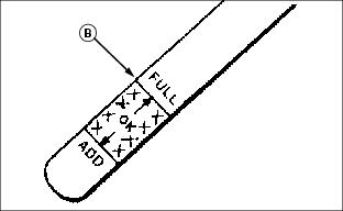
6. Add oil through dipstick tube to bring level to the FULL mark (B) on dipstick.
· Approximate crankcase capacity for Models 924DE, 1128DE and 1128DDE: 769 mL (26 oz)
· Approximate crankcase capacity for Models 1332DDE: 828 mL (28 oz)
7. Install and tighten dipstick.
Cleaning And Gapping Spark Plug
1. Clean area around spark plug.
2. Disconnect spark plug wire (A).
· Pitted of damaged electrodes.
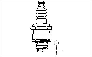
5. Check plug gap (B) with a feeler gauge:
· Gap must be 0.76 mm (0.030 in.).
6. Install spark plug and tighten to 25 - 32 N·m (220 - 280 lb-in).
Cleaning Cylinder Fins
· Every 100 operating hours or yearly (more often if conditions require) remove cooling shrouds and clean cooling fins.
· Also clean external surfaces of your engine of dust, dirt, and oil deposits which can contribute to improper cooling.
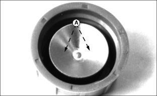
Replacing Shear Bolts
NOTE: Two extra shear bolts were included with your snowblower.
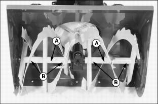
2. Remove broken shear bolt (A), if necessary.
3. Lubricate auger shaft at four points (B). Turn auger shaft several times to distribute grease.
4. Line up holes in auger with hole in auger shaft.
5. Install new shear bolt and lock nut.
Adjusting Carburetor
NOTE: The carburetor is calibrated by the engine manufacturer and should not require any adjustments.
If engine is operated at altitudes above 1829 m (6,000 ft.), see your John Deere dealer.
Possible engine surging will occur at high rpm when the transmission is in neutral ("N") and auger drive is disengaged. This is a normal condition due to the emission control system.
If engine is hard to start or runs rough, check the Troubleshooting section of this manual.
After performing the checks in the troubleshooting section and your engine is still not performing correctly, contact your John Deere dealer.
Draining Carburetor
1. Turn fuel shut off valve (A) to the CLOSED (OFF) position.
2. Place a small container under the carburetor.
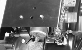
3. Press drain plug (B) in until all fuel is removed from bowl.
Lubricating Auger Gearbox
NOTE: Two different types of gear boxes are used. Both are serviced the same way.
1. Clean area around fill plug.
2. Park unit on level surface.
4. Fluid level should be at oil fill plug.
Lubricating Auger Shaft
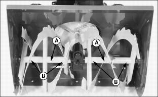
2. Turn auger on shaft while applying grease to grease fittings (B).
Lubricating Internal Drive
1. Park snowblower on a hard, smooth surface.
2. Stop engine, remove key, wait for all moving parts to stop.
3. Remove wire from spark plug to prevent accidental starting.

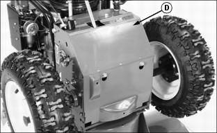
5. Tip machine forward onto housing (A).
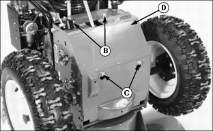
6. Remove two bolts (B) and loosen two bolts (C) to remove access panel (D).
IMPORTANT: Avoid damage! DO NOT allow grease or oil to get on friction wheel (E), drive disc or belts. |
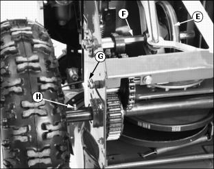
7. Apply grease to hex shaft (F), pinion shaft grease fitting (G) and both drive axle grease fittings (H).
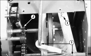
8. Lightly apply oil to shift lever arm pivot points (I) and drive chain (J).
9. Install access panel (D) and tighten hardware.
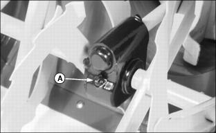
Lubricating Discharge Chute
Turn discharge chute while applying grease to base (A).
Changing Auger Drive Belt
1. Park snowblower on a hard, smooth surface.
2. Stop engine, remove key, wait for all moving parts to stop.
3. Remove wire from spark plug to prevent accidental starting.

5. Tip machine forward onto housing (A).

6. Remove two bolts (B) and loosen two bolts (C) to remove access panel (D). This will prevent the access panel from being bent when unit is split.
7. Tip unit back to it's normal position.
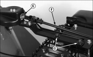
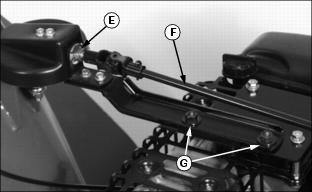
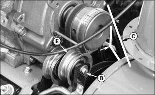
8. Remove quick pull pin (E) and remove chute crank rod (F).
9. Remove both cap screws and lock nuts (G), lay discharge chute assembly off to the right side of the unit.

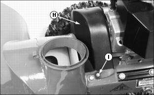
10. Remove two cap screws (I) to remove belt cover (H).

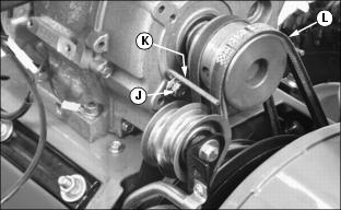
11. Loosen cap screw (J) just enough to loosen belt guide (K).
12. Move belt guide enough to remove auger drive belt (L) from engine drive sheave.
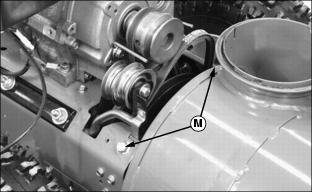
IMPORTANT: Avoid damage! To prevent damage to engine frame and components, hold onto handlebars when removing frame bolts. |

13. Remove two cap screws (M).
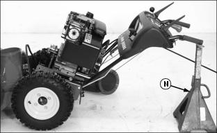
14. Place a support (N) under handlebars and slowly lean back engine frame.
15. Lean back engine frame only far enough to expose the auger drive belt.
16. Put handle bars on support (N).
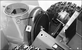
17. Remove auger drive belt (O) and install new belt.
18. Put unit back together and tighten two cap screws.
19. Install auger drive belt onto engine drive sheave.
20. Check auger drive belt tension and adjust if necessary.
21. Install belt guide and hardware.
22. Install belt cover and hardware.
23. Install discharge chute assembly and connect chute crank rod.
Changing Traction Drive Belt
1. Park snowblower on a hard, smooth surface.
2. Stop engine, remove key, wait for all moving parts to stop.
3. Remove wire from spark plug to prevent accidental starting.

5. Tip machine forward onto housing (A).

6. Remove two bolts (B) and loosen two bolts (C) to remove access panel (D). This will prevent the access panel from being bent when unit is split.
7. Tip unit back to it's normal position.
8. Remove quick pull pin (E) and remove chute crank rod (F).
9. Remove both cap screws and lock nuts (G), lay discharge chute assembly off to the right side of the unit.
10. Remove two cap screws (I) to remove belt cover (H).
11. Loosen cap screw (J) just enough to loosen belt guide (K).
12. Move belt guide enough to remove auger drive belt (L) from engine drive sheave.
IMPORTANT: Avoid damage! To prevent damage to engine frame and components, hold onto handlebars when removing frame bolts. |
13. Remove two cap screws (M).

14. Place a support (N) under handlebars and slowly lean back engine frame.
15. Lean back engine frame only far enough to expose the auger drive belt.
16. Put handle bars on support (N).
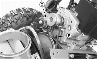
17. Pull back spring loaded idler (O) and remove traction drive belt (P) from engine drive sheave. Install new belt.
18. Put unit back together and tighten two cap screws.
19. Install auger drive belt onto engine drive sheave.
20. Check auger drive belt tension and adjust if necessary.
21. Install belt guide and hardware.
22. Install belt cover and hardware.
23. Install discharge chute assembly and connect chute crank rod.
Adjusting Auger Drive Belt Tension
1. Park snowblower on a hard, smooth surface.
2. Stop engine, remove key, wait for all moving parts to stop.
3. Remove wire from spark plug to prevent accidental starting.
4. Remove two cap screws (A) to remove belt cover (B).
5. Hold down the auger drive lever in the engaged position while checking belt tension.
6. Check drive belt deflection (C). Belt should deflect a little with moderate thumb pressure.
· Move pulley (E) toward belt to tighten or away to loosen. Hold pulley and tighten nut.
8. Check belt deflection again.
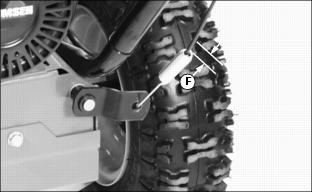
· When the drive belt is properly tensioned, cable spring should extend approximately 9.5 mm (3/8 in.) (F), with auger drive lever engaged.
· When the auger drive lever is disengaged, pulley (E) should drop away from the drive belt.
9. Install belt cover and two cap screws.
Adjusting Chute Crank
1. Park snowblower on a hard, smooth surface.
2. Stop engine, remove key, wait for all moving parts to stop.
3. Remove wire from spark plug to prevent accidental starting.
· If chute crank is too loose, tighten nut (A).
· If chute crank is too tight, loosen nut (A).
Checking Clutch / Impeller Brake
1. Park snowblower on a hard, smooth surface.
2. Stop engine, remove key, wait for all moving parts to stop.
3. Remove wire from spark plug to prevent accidental starting.

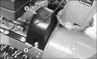
5. Tip machine forward onto housing (A).

6. Remove two bolts (B) and loosen two bolts (C) to remove access panel (D).
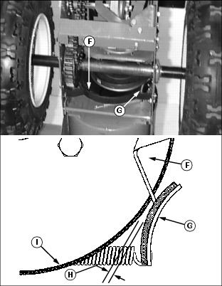
7. Check clearance (H) between brake pad (G) and auger drive belt (I) on auger drive sheave (F):
· With auger drive lever engaged, clearance (H) should be approximately 1.5 mm (1/16 in.).
· With auger drive lever released, the brake pad (G) must contact auger drive belt (I).
8. If proper clearance can not be obtained see your John Deere Dealer.
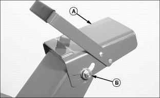
Adjusting Chute Deflector Lever- Models 1128DE, 1128DDE and 1332DDE
1. Park snowblower on a hard, smooth surface.
2. Stop engine, remove key, wait for all moving parts to stop.
3. Remove wire from spark plug to prevent accidental starting.
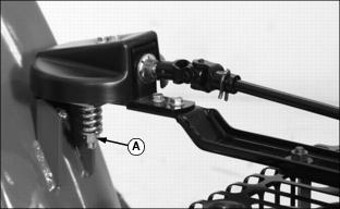
4. Check chute deflector lever (A) and adjust if necessary.
5. Adjust chute deflector lever:
· If lever is too loose, tighten nut (B).
· If lever is too tight, loosen nut (B).
Adjusting Chute Deflector - Model 924DE
1. Park snowblower on a hard, smooth surface.
2. Stop engine, remove key, wait for all moving parts to stop.
3. Remove wire from spark plug to prevent accidental starting.
4. Check chute deflector (A) and adjust if necessary.
· If chute deflector is too loose, tighten nut (B).
· If chute deflector is too tight, loosen nut (B).
Adjusting Traction Drive Clutch
Adjust traction clutch to compensate for wear of friction wheel when slippage occurs.
1. Park snowblower on a hard, smooth surface.
2. Stop engine, remove key, wait for all moving parts to stop.
3. Remove wire from spark plug to prevent accidental starting.

5. Tip machine forward onto housing (A).
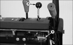
6. Put speed selector lever (B) in FIRST gear.
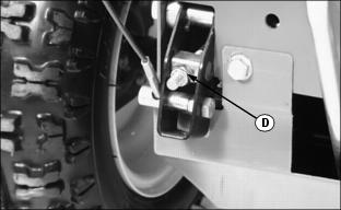
7. With traction clutch lever (C) disengaged, turn drive wheels by hand. Tighten adjustment nut (D) until wheels begin to drag.
8. Engage and release traction clutch lever (C) to align clutch linkage.
9. Repeat procedure as necessary.
10. When wheel drag is obtained with linkage alignment, loosen adjustment nut (D) a full three turns. Drive wheels will then turn freely.
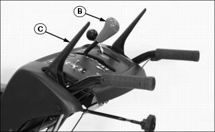
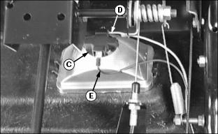
Adjusting Speed / Shift Linkage
1. Park snowblower on a hard, smooth surface.
2. Stop engine, remove key, wait for all moving parts to stop.
3. Remove wire from spark plug to prevent accidental starting.
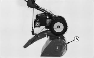
5. Tip machine forward onto housing (A).
6. Move speed selector lever (B) to the "6" (6th gear) position.
7. Locate shift rod under operator control panel.
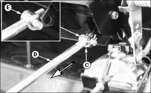
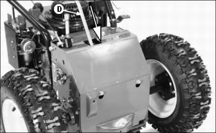
8. Remove quick pull pin (C) from shift rod (D) and remove shift rod assembly from shift lever linkage.
9. Push shift rod (D) into housing as far as it will go and hold it in this position until rod adjustment is made.
10. Turn adjusting link (E) until stud aligns with hole in shift linkage.
11. Install shift rod (D) into shift lever linkage and install quick pull pin (C).
12. Return unit to its operating position.
13. Start engine and check for proper operation of the speed selector lever (B).
Adjusting Drive Chain
1. Park snowblower on a hard, smooth surface.
2. Stop engine, remove key, wait for all moving parts to stop.
3. Remove wire from spark plug to prevent accidental starting.

5. Tip machine forward onto housing (A).

6. Remove two bolts (B) and loosen two bolts (C) to remove access panel (D).
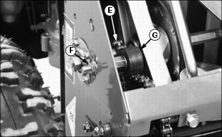
7. Drive chain (E) should be taut with little or no play in it.
8. To adjust chain tightness: Loosen nut (F) and move chain tensioner (G) up or down in slot as necessary.
Filling Fuel Tank
Use regular grade 87 octane unleaded fuel.
Add John Deere fuel stabilizer to fuel before using it in your machine to prevent engine damage due to stale fuel. Follow directions on stabilizer container.
1. STOP engine, let it cool several minutes before you add fuel.
2. Remove dirt and debris from tank area.
4. Fill tank with fuel only to bottom of filler neck.
Cleaning Fuel Cap Vents
· Clean in nonflammable solvent.
Changing Headlight Light Bulb
1. Stop engine, remove key, wait for all moving parts to stop.
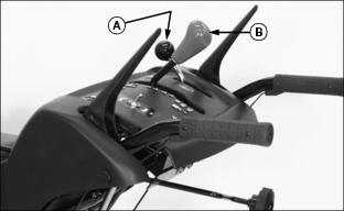
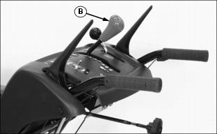
2. On Models 1128DE, 1128DDE and 1332DDE, move chute deflector lever (A) to the rear.
3. Move shift lever (B) to the "R2" position.
NOTE: It is not necessary to disconnect the green wire (D) or the black wire (E) to remove the light bulb holder.
4. Turn light bulb holder (C) counterclockwise 1/4 of a turn and remove it from the headlight.
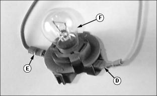
5. Turn light bulb (F) counterclockwise 1/4 of a turn and remove it from the holder.
6. Remove and replace defective light bulb (F).
7. Install light bulb holder. Turn clockwise 1/4 of turn to tighten.