Introduction
Product Identification
Safety
Operating
Replacement Parts
Service Intervals
Service Lubrication
Service Engine
Service Transmission
Service Steering & Brakes
Service Mower
Service Electrical
Service Miscellaneous
Troubleshooting
Storage
Assembly
Specifications
Warranty
John Deere Quality Statement
Service Record
CopyrightŠ Deere & Company

Service Steering & Brakes
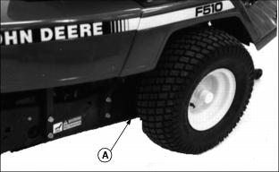
Removing Front Wheels
IMPORTANT: Avoid damage! Do not put jack under fender deck to raise a wheel. Do not use drawbar as a jack point. |
1. Install jack under frame at point (A).
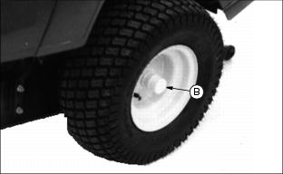
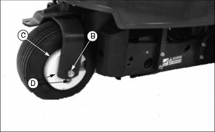
2. Remove yellow protective cap (B).
6. Install wheel bolt and tighten bolt to 40-60 Nˇm (30-45 lb-ft).
7. Install yellow protective cap.
Removing Rear Wheel
1. Turn steering wheel so rear wheel points straight ahead.
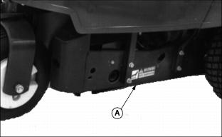
2. Install jack under frame at point (A).
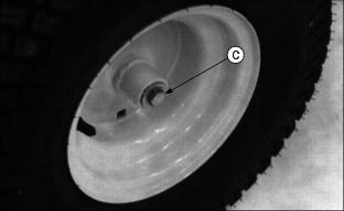
5. Remove wheel weights (C) by removing two bolts (D).
8. Install wheel bolt and tighten.
Adjusting Brake Linkage
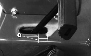
2. Measure distance (A) from pedal rod to end of slot.
4. Push pedal down slowly. Hold pedal when you feel resistance. As you hold pedal, measure (A) again. Difference between two measurements should be 15 mm (9/16 in).
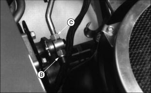
5. If not, lift seat. Loosen nut (C).
6. Turn nut (B) to adjust linkage for correct measurement.
7. Tighten nut (C). Lower seat.
8. Test brake pedal action to determine if adjustment is correct.

