![]()
Introduction
Product Identification
Safety
Operating
Replacement Parts
Service Intervals
Service Lubrication
Service Engine
Service Transmission
Service Steering & Brakes
Service Mower
Checking Gauge Wheel Tire Pressure
Replacing Front Roller (48-in. Deck)
Adjusting Mower For 102 mm (4-in.) Cutting Height
Service Electrical
Service Miscellaneous
Troubleshooting
Storage
Assembly
Specifications
Warranty
John Deere Quality Statement
Service Record
Copyright© Deere & Company

Service Mower
Removing Mower

Picture Note: Early model shown.
1. Crank mower to highest position by using crank (A).
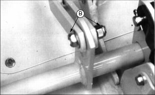
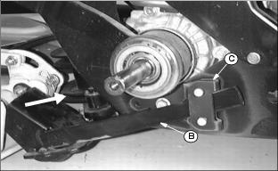
2. Remove cable end from mower by removing spring locking pin and drilled pin (B). Install drilled pin and spring locking pin back into lift linkage arm after removing cable.
3. Crank mower all the way down.

Picture Note: New model shown.
4. Pivot handle (C) clockwise to release belt tension.
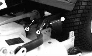
5. Remove spring (D) from handle.

6. Remove mower (upper) belt (E) from top sheave (F).
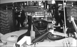
7. Reach under frame behind drive wheel and remove engine (lower) belt from engine sheave (G).

8. Remove each push arm from mower by removing spring locking pin (H) and drilled pin (I).
9. Install drilled pin and spring locking pin back into mower bracket after removing push arms.
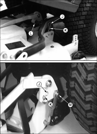
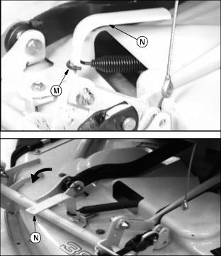
Picture Note: Early model shown in top picture. New model shown in bottom picture.
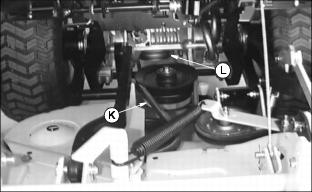
10. Remove spring locking pin (J) and long pin (K).
11. Remove center arm bushing (L) on left push arm.
12. On new model only: Remove drilled pin (M) and spring locking pin from yoke.
13. Install long pin and spring locking pin back into left push arm.

14. Use straps (N) or ropes to hold push arms up for ease in removing mower from Front Mower.
15. Pull mower out from under Front Mower unit.
Installing Mower
IMPORTANT: Avoid damage! Improper installation of jacksheave pivot arm will cause belt rubbing on frame cross member and will shorten belt life. |
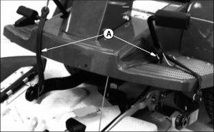
1. Use straps (A) or ropes to hold push arms up for ease in installing mower to Front Mower.

2. Push mower under Front Mower unit. Slide jacksheave pivot arm (B) into chassis pivot bracket (C) on Front Mower frame.
Picture Note: Left wheel removed for picture.
Picture Note: Early model shown.
3. Install center arm bushing (D) on left push arm and fasten with long pin (E) and spring locking pin (F).

Picture Note: New model shown.
4. On New model only: Fasten yoke (G) to push arm with drilled pin (H) and spring locking pin.
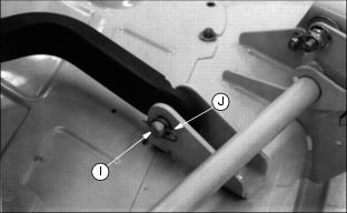
5. Install each push arm on mower and fasten with drilled pin (I) and spring locking pin (J).
6. Install engine (lower) belt (K) on engine sheave (L).
Picture Note: Early model shown.
7. Install spring (M) on handle and pivot handle (N) counterclockwise to tighten belt.
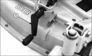
8. Crank mower to the highest position by using mower crank (O).
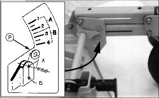
9. Determine what height mower deck will be set at and check label (P) so that the weight transfer cable can be connected in it's correct position. This will ensure proper operation of the Weight Transfer System.
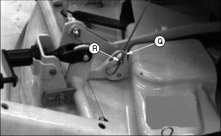
Picture Note: Early model shown.
10. Install cable end on mower and fasten with drilled pin (Q) and spring locking pin (R).
11. Rotate belt to check if belt is seated on all sheaves and pulleys.
Cleaning Mower Belt Area
Check belt area regularly for buildup of clippings.
NOTE: Make sure center link is pivoted forward.

Picture Note: Early model 38 in. deck shown in top picture, early model 48 in. deck shown in bottom picture.
2. Remove belt shields by removing (38-in. deck) or loosening (48-in. deck) six cap screws (A) holding belt shields.
5. Clean and inspect belt for damage.
6. Clean upper mower deck and sheaves.
Checking Gauge Wheel Tire Pressure
Pressure for gauge wheel tires: 310 kPa (45 psi).
Replacing Mower Belt
1. Park the machine safely. (See Park Safely in the Safety section.)
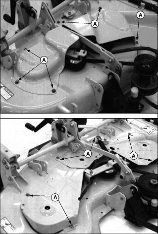
Picture Note: Early model 38 in. deck shown in top picture, early model 48 in. deck shown in bottom picture.
· 38-in. deck: Remove six screws (A).
NOTE: Remove center shield first.
· 48-in. deck: Loosen six screws (A).
NOTE: If mower drive belt was removed, install new belt on jacksheave as shown.
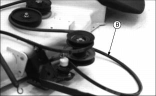
5. Check mower drive belt (B). If necessary, replace this belt at the same time.

Picture Note: Early model 38-in. deck shown in top picture. Early model 48 in. deck shown in bottom picture.
6. Install new mower belt (C) (highlighted with dashed line).
7. Install and fasten belt shields:
NOTE: Make sure belt is seated on every sheave and pulley before installing shields.

Picture Note: Early model 38 in. deck shown in top picture, early model 48 in. deck shown in bottom picture.
· 38-in. deck: Install and tighten six screws (D).
NOTE: Install center shield last.
· 48-in. deck: Tighten six screws (D).
8. Install mower on Front Mower.
Servicing Mower Blades
Removing Mower Blades
1. Remove mower deck and turn upside down.
2. Put a block of wood under each side of mower.
3. Place a block of wood between blade and deck to prevent blade from turning when removing bolt.
4. Remove bolt, washer and blade.
5. If blade is dull, have it sharpened and balanced.
6. If blade is damaged, install a new blade.

7. Fasten new or sharpened blade with washer and bolt (A). Make sure cupped side of washer is next to blade.
8. Tighten bolt to 75 N·m (55 ft-lb).
Installing Mower Blade
1. Lubricate bolt threads lightly with a general purpose grease or oil. This lubrication is to prevent rusting and seizing.
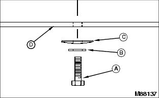
2. Position mower blade (D) with the cutting edge towards the ground onto the mower spindle.
3. Install blade washer (C) with cup side toward the blade, hardened washer (B) and cap screw (A).
4. Tighten cap screw (A) by hand until mower blade is in full contact (fully seated) with spindle.
5. Block mower blade with a piece of wood to prevent spinning, tighten cap screw to 68 - 75 N·m (45-55 lb-ft).
Sharpening Blades
Sharpen blades with grinder, hand file, or electric blade sharpener.
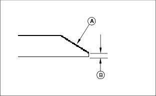
Keep original bevel (A) when grinding.
Blade should have 0.40 mm (1/64 in.) cutting edge (B) or less.
Balance blades before installing.
Balancing Blades

2. Put blade on nail in a vise. Turn blade to horizontal position.
3. Check balance. If blade is not balanced, heavy end of blade will drop.
4. Grind bevel of heavy end. Do not change blade bevel.
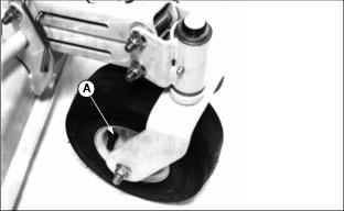
Replacing Front Roller (48-in. Deck)

1. Remove hardware (A) from left side of roller shown.
3. Install new roller on shaft.
NOTE: Inspect front roller washer (B) for replacement before installing new roller.
Replacing Rear Roller

1. Remove yellow protective cap (A).
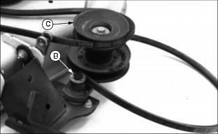
2. Remove snap ring and washer (B).
3. Remove jacksheave assembly (C).
NOTE: There are two washers located underneath jacksheave. Check to be sure washers are in place before installing jackshaft.
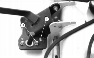
4. Loosen two carriage bolts (D).
5. Remove roller retaining pin (E).
8. Tighten hardware loosened above.
9. Install jacksheave assembly and hardware.
10. Install yellow protective cap.
Replacing Jacksheave Bushings
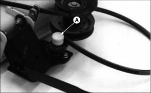
1. Remove yellow protective cap (A).
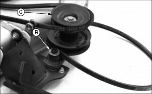
2. Remove snap ring and washer (B).
3. Remove jacksheave assembly (C).
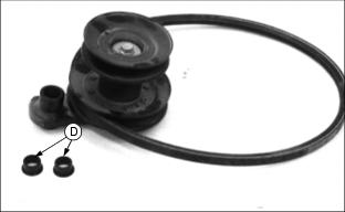
4. Remove two black plastic bushings (D).
6. Put jacksheave on pivot arm (E).
7. Install washer and snap ring removed above.
8. Install yellow protective cap.
Adjusting Mower For 102 mm (4-in.) Cutting Height

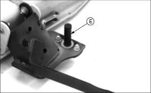
If you cannot adjust mower to 102 mm (4-in.) cutting height by turning crank, follow steps below:
1. Raise and block front of mower so front wheels are off the ground.
2. Make sure bracket (A) is against shaft (B) as shown.