Introduction
Product Identification
Safety
Operating
Replacement Parts
Service Intervals
Service Lubrication
Service Engine
Service Transmission
Service Steering & Brakes
Service Mower
Service Electrical
Service Miscellaneous
Troubleshooting
Storage
Assembly
Install Console Cap And Steering Wheel
Specifications
Warranty
John Deere Quality Statement
Service Record
CopyrightŠ Deere & Company

Assembly
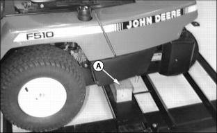
Remove Bracing
Raise rear of Front Mower approximately 50 mm
(2 Inches) with safe lifting device to allow removal of wooden shipping brace (A) from under unit. Turn and pull brace from below unit and discard. Lower Front Mower completely to crate bottom.
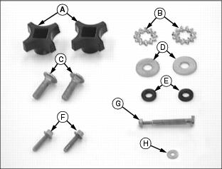
Identify Parts
Bag of Parts
Install Seat
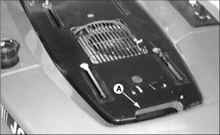
1. Lift seat base at the cut-out hand-hold area (A) and raise until it latches in the first or second position.
Picture Note: Shown from underside of seat base.
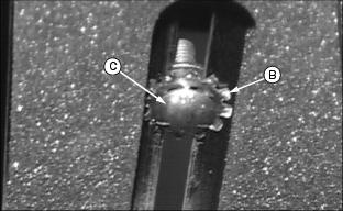
2. Place star washer (B) on carriage bolt (C) and install from bottom through front slot in seat base.
NOTE: Rubber washer should hold carriage bolt and washers in place in slots while seat assembly is installed to seat base.
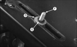
3. Install metal washer (D) and rubber washer (E) to carriage bolt (F). Do for both front slots in seat base.
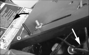
4. Lower seat base by lifting base slightly at the cut-out hand-hold area at the rear of the seat base. Push and hold seat release lever (G) forward while lowering seat base.
NOTE: Flange of seat rail bolt must be below seat base when properly installed.
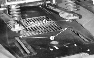
5. Hold seat assembly above seat base and insert protruding bolt heads (H) at rear of seat rails into rear slots (I) of seat base.
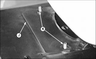
6. Slide seat assembly to the rear of the seat base and align holes at front of seat base (J) with carriage bolts (K). Place seat base over carriage bolts.
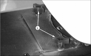
7. Turn seat adjustment knobs (L) onto carriage bolts and tighten.
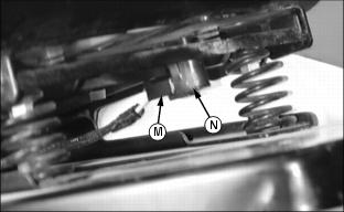
8. Attach wiring harness plug (M) protruding through seat base to seat safety switch (N) on underside of seat.
Connect and Check Battery
IMPORTANT: Avoid damage! To prevent damage to tractor electrical system the battery cables must be installed correctly. |
1. Battery is filled with acid and charged when it left the factory. To extend battery life, charge the battery prior to delivery. Check battery voltage. Battery should be charged if voltage is below 12.3 volts. Battery is fully charged at 12.6 volts.
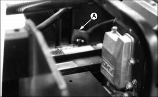
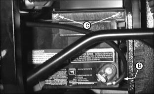
2. Connect red positive (+) cable (A) to battery. Apply petroleum jelly or silicone spray to terminal to prevent corrosion. Make sure connection is tight. Push red positive cover over positive terminal.
NOTE: Make sure black negative cable is routed behind red positive cable
3. Connect black negative (-) cable (B) to battery. Apply petroleum jelly or silicone spray to terminal to prevent corrosion. Make sure connection is tight.
4. Check two battery hold down cap screws (C) for tightness, tighten if necessary.
Install Console Cap And Steering Wheel
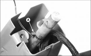
1. Remove steering console cap from bag. Cut and discard tie strap (A) securing steering shaft to console.
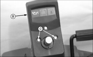
2. Install console cap (B) onto console with steering shaft through center hole. Secure with two M6 x 25 flange head bolts (C).
3. Put rear wheel in the straight-ahead position.
4. Install steering wheel on shaft with John Deere logo in the upright position and center spoke to rear. Align steering wheel hole with hole in shaft.
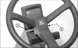
5. Install special bolt (D) through steering wheel and shaft. Drive bolt in until head contacts steering wheel.
6. Fasten bolt with washer and lock nut (E).

