![]()
Introduction
Product Identification
Safety
Operating
Replacement Parts
Service Interval Chart
Service Engine
Changing Engine Oil and Filter
Checking Air Restriction Indicator
Cleaning Radiator Screen and Fins
Checking Fuel Filter Sediment Bowl
Cleaning Fuel Filter Sediment Bowl
Replacing Primary Air Cleaner Element
Replacing Secondary Air Cleaner Element
Service Transmission
Service Lubrication
Service Electrical
Service Miscellaneous
Troubleshooting
Storing Machine
Assembly
Specifications
Warranty
John Deere Quality Statement
Service Record
Copyright© Deere & Company

Service Engine
Avoid Fumes

· If it is necessary to run an engine in an enclosed area, use an exhaust pipe extension to remove the fumes. |
Engine Oil
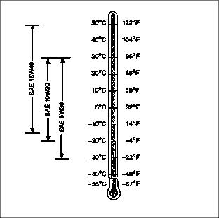
Use oil viscosity based on the expected air temperature range during the period between oil changes.
The following oil is preferred:
· John Deere PLUS-50®- SAE 15W40
The following John Deere oils are also recommended if the above preferred oil is not available:
· TORQ-GARD SUPREME® - SAE 5W30
If John Deere PLUS-50® engine oil and a John Deere oil filter are used, the oil and filter service interval may be extended by 50 hours.
Other oils may be used if the John Deere oils listed are not available, provided they meet one of the following specifications:
· SAE 15W40 - API Service Classification CG-4, CF-4, CF, or MIL-L-46152B
· SAE 10W30 - API Service Classification CF-4, CF, or Military Specification MIL-L-2104F
· SAE 5W30 - API Service Classification CF
If diesel fuel exceeding 0.5% sulfur content is used, reduce the service interval for engine oil and filter by 50%.
Arctic oils (such as SAE 0W30 or Military Specification MIL-L-46167B) may be used if temperatures fall below -30°C (-22°F), but reduce the oil change interval by 50%.
Checking Engine Oil Level
1. Park vehicle on a level surface.
2. Check engine oil when oil is cold.

Picture Note: Left hand side panel removed for photo clarity.
4. Remove dipstick (A). Wipe dipstick with a clean rag.
5. Install dipstick. Be sure dipstick is all the way down.
6. Remove dipstick. Check oil level on dipstick.
7. Oil level should be between (C) and (D) on dipstick.
NOTE: This engine is equipped with two oil filler caps, either filler cap can be used.

8. Oil level should be between (C) and (D) on dipstick.

Picture Note: Left hand side panel removed for photo clarity.
9. If oil level is low, remove oil filler cap (B).
10. Add oil to bring oil level no higher than (C) on dipstick.
12. Install and tighten oil filler cap.
Changing Engine Oil and Filter
IMPORTANT: Avoid damage! Change engine oil and filter after first 50 hours of break-in operation. When operating vehicle in extremely dusty or dirty conditions, change engine oil more often. |
1. Park vehicle on a level surface.
2. Run engine a few minutes to warm oil.

6. Route oil drain hose (A) to allow draining into oil pan.
7. Open drain valve (B) by turning it counterclockwise.
8. Drain oil in pan. While oil is draining, change oil filter.
9. Remove left-hand side panel.
NOTE: Be sure to put a oil drain pan under filter also.

10. Remove filter (C) using a filter wrench. Turn filter counterclockwise.
11. Apply a film of clean engine oil on seal of new filter.
12. Install filter. Turn filter until seal contacts mounting surface. Then turn filter by hand 1/2 turn more.
13. Install left-hand side panel.
15. Remove right-hand side panel.

16. Return oil drain hose (D) to inside of frame. Be sure hose rests next to the battery on the battery platform.
17. Install right-hand side panel.
NOTE: This engine is equipped with two oil filler caps, either filler cap can be used.

18. Remove filler cap (E). Add approximately 2.8 L (3.0 qt) of oil.

19. Remove dipstick (F) to check oil level. Oil level should be between (G) and (H), but not higher than (G).
20. Install and tighten filler cap.
22. Start engine and run at slow speed for two minutes. Check for leaks around filter and drain plug.
23. Stop engine. Check oil level.
24. Install dipstick. Install left-hand side panel. Lower hood.
Cleaning Air Intake Screens
IMPORTANT: Avoid damage! Side panel intake screens must be clear of dirt and debris to prevent engine from overheating and to allow good air intake for air cleaner. |

Clean air intake screens (A) on side panels using a brush or cloth.
Checking Air Restriction Indicator
NOTE: Indicator will not signal correctly if indicator case is cracked or broken.

3. Check air restriction indicator: When yellow plunger (B) inside indicator reaches red line (A), air cleaner requires immediate service.
Cleaning Radiator Screen and Fins

3. Clean screen with a brush or compressed air.
4. Remove right-hand side panel.

5. Clean radiator cooling fins (B) using compressed air or water.
Service Cooling System Safely
Engine Coolant
The following John Deere coolants are preferred:
· COOL-GARD PRE-DILUTED SUMMER COOLANT (TY16036).
· COOL-GARD CONCENTRATED SUMMER COOLANT (TY16034).
If neither of the recommended coolants is available, use a glycol base coolant that meets the following specification:
Check container label before using to be sure it has appropriate specifications for your machine. Use coolant with conditioner or add conditioner to coolant before using.
If using concentrate, mix approximately 50 percent antifreeze with 50 percent distilled or deionized water before adding to cooling system. This mixture will provide freeze protection to -37 degrees C (-34 degrees F).
Certain geographical areas may require lower temperature protection. See the label on your antifreeze container or consult your John Deere dealer to obtain the latest information and recommendations.
Engine Coolant Drain Interval
When using COOL-GARD PRE-DILUTED SUMMER COOLANT (TY16036) or COOL-GARD CONCENTRATED SUMMER COOLANT (TY16034), Automobile and Light Duty Engine Service coolants, drain and flush the cooling system and refill with fresh coolant mixture every 24 months.
If above John Deere Automobile and Light Duty Engine Service coolants are not being used; drain, flush, and refill the cooling system according to instructions found on product container or in equipment Operator's Manual or Technical Manual.
Checking Coolant Level

· If engine is warm (into green range on temperature gauge), coolant should be between lines (A) and (B) on coolant tank.
· If engine is cold, coolant should be above line (C).

3. If coolant is low, remove coolant recovery tank cap (D). Add ethylene glycol antifreeze (without stop-leak additive) and water in a 50:50 ratio to the bring coolant up to the proper level.
4. Install and tighten coolant recovery tank cap.
5. Clean debris from side panel air intake screens and radiator screen.
6. Check condition of hoses. Check for leaks or loose connections.
Draining Cooling System
1. Stop engine. Let engine cool.

3. Slowly remove radiator cap (A).
4. Remove left-hand side panel.

5. Open radiator petcock (B). Drain coolant into a bucket (C).

6. Loosen bolt (D) to move fuel filter away from block drain plug bolt.

7. Remove drain plug bolt (E) to drain coolant from engine block.
8. After all coolant has drained, close radiator petcock and install block drain plug bolt. Install fuel filter.
Flushing Cooling System
IMPORTANT: Avoid damage! Using incorrect coolant mixture can damage the radiator: · DO NOT operate engine with plain water. · DO NOT pour coolant or water into the radiator when the engine is hot. |
NOTE: Cooling system capacity is 2.8 L (3.0 qt).
1. Fill cooling system with clean water and John Deere Cooling System Cleaner, or John Deere Cooling System Quick Flush or an equivalent. Follow directions on can.

2. Install and tighten radiator cap (A).
3. Start and run engine until it reaches operating temperature.
5. Drain cooling system immediately into a pan or proper container before rust and dirt settle.

· Pull overflow hose (C) from tank.
10. Install overflow hose to the bottom of the tank. Be sure hose is not kinked.
Filling Cooling System
NOTE: John Deere COOL-GARD coolant is recommended when adding new coolant to the cooling system.
Follow the directions on the container for correct mixture ratio.
2. Check condition of cooling system hoses.
3. Install new hoses, if necessary.
4. Fill cooling system. Cooling system capacity is 2.8 L (3.0 qt).
5. Install and tighten radiator cap.
6. Run engine until needle on temperature gauge reaches the green range.

8. Coolant level should be between lines (A) and (B) on coolant tank. After engine cools, level should be above line (C).

9. Remove cap (D) to add coolant if necessary.
10. Tighten hose clamps, if necessary.
Adjusting Fan Belt Tension
2. Raise hood and remove right-hand side panel.
3. Inspect Belt - Check belt for wear and cracking, replace if necessary.

4. Check belt tension by pressing lightly on belt (A) between alternator and fan pulleys. Belt should deflect approximately 13 mm (1/2 in.).
b. Loosen alternator bolts (C).
c. Push alternator (D) up to loosen belt, and down to tighten belt.
f. Replace belt if it is damaged.
g. Install right-hand side panel. Lower hood.
Replacing Fan Belt
NOTE: Rotate driveshaft for access to bolts, if necessary.

2. Remove three bolts (B) to disconnect drive shaft (A).
3. Remove belt (C) from engine sheave, and alternator and fan pulleys. Pull belt over fan.
4. Install new belt loosely around sheave and pulleys.
Checking Fuel Filter Sediment Bowl
2. Remove left-hand side panel.

3. Check for water in sediment bowl (A): Orange ring will float on top of the water.
4. Clean bowl before orange ring reaches bottom of filter.
Cleaning Fuel Filter Sediment Bowl
1. Raise hood and remove left-hand side panel.

3. Turn collar (A) to remove bowl and filter. Discard filter.
5. Install new filter and bowl.
7. Install side panel and lower hood.
8. Start tractor and check for leaks.
Replacing Primary Air Cleaner Element
IMPORTANT: Avoid damage! DO NOT clean primary air cleaner element. Replace it when air restriction indicator reaches red line. |

2. Remove wing nut (A) and cover (B).

4. Remove and discard primary element (D).
NOTE: Be sure negative battery cable is behind cover valve.
5. Install new primary element and wing nut. Be sure wing nut is tight.
6. Install cover and tighten wing nut.

Picture Note: Left hand side panel removed for photo clarity
9. Push in button (E) to reset air restriction indicator.
11. Start engine, stop engine, raise hood, and check indicator. Yellow plunger should be below the 330 mm (13 in.) mark. If indicator shows more than 330 mm (13 in.) vacuum, replace secondary element.
Replacing Secondary Air Cleaner Element

2. Remove wing nut (A) and secondary element (B). Discard element.
3. Install new element and wing nut. Be sure wing nut is tight.
4. Install primary element and wing nut. Be sure wing nut is tight.
NOTE: Be sure negative battery cable is behind cover valve.
5. Install cover and tighten wing nut.
7. Reset air restriction indicator.
Adjusting Fuel Injection Pump
NOTE: The fuel injection pump is calibrated by the engine manufacturer and should not require any adjustments.
If engine is hard to start, lacks power, or runs rough, check the TROUBLESHOOTING section of this manual.
After performing the checks in the troubleshooting section if your engine is still not performing correctly, contact your John Deere dealer.