![]()
Introduction
Product Identification
Safety
Preparing Vehicle
Installing
Removing
Operating
Troubleshooting
Assembly
Identify Parts (SST Lawn Tractors)
Identify Parts (STX, LT, LX, GT Series Tractors)
Install Mounting Kit (BM19211) (STX's, LX277-AWS, 325, 345, and GT Series Tractors Only)
Assembly (STX Model and LX Lawn Tractors Without Bagger Attachment)
Assembly for GT Series, 325, and 345 Lawn and Garden Tractors
Assembly for LX Lawn Tractors With Bagger Attachment
Specifications
John Deere Quality Statement
Copyright© Deere & Company

Assembly
Identify Parts (SST Lawn Tractors)
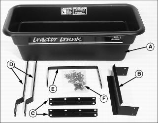
Box of Parts
Bag of Parts
Assembly (SST Lawn Tractors)
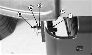
Assemble Latch Lever
1. Position dump latch lever with notches (A) facing up.
2. Install one 5/16x1-1/4 in. hex head bolt (B) on each side of dump latch lever. Install one 5/16 in. flanged hex nut on each bolt with flanged end (C) of nut facing away from latch lever. Tighten both nuts, but allow bolts to move in lever holes.
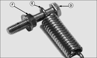
3. Install 1/4x1-1/2 in. hex head bolt (D) through end of spring (E). Install 1/4 in. flanged hex nut (F) with flanged end away from bolt head. Turn nut completely to end of bolt threads.
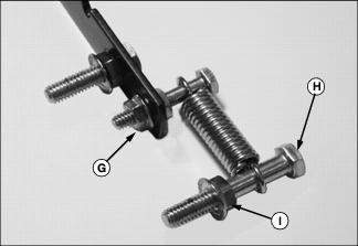
4. Install hex head bolt with spring attached through end hole in lever. Install and tighten remaining 1/4 in. flanged hex nut (G).
5. Install 5/16x2 in. hex head bolt (H) on other end of spring. Install 5/16 in. flanged hex nut (I) with flanged end away from bolt head. Turn nut completely to end of bolt threads.
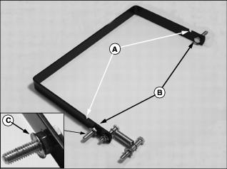
Attach Latch Lever to Support Assembly
NOTE: Notches on latch lever must face away from tractor and toward trunk. Longer ends of support rails face away from tractor. Install support rails inside drawbar support frame.
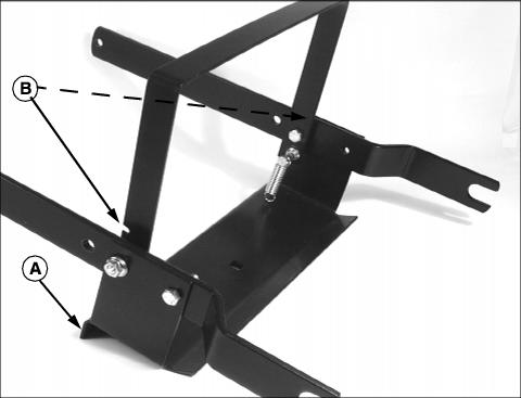
Picture Note: completed assembly shown
1. Position drawbar support frame so edge that bends down (A) is toward longer ends of support rails. Position latch lever so notches (B) face toward longer ends of support rails.
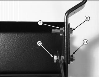
2. Install right latch lever bolt (C) through right support rail and drawbar support frame. Install 5/16 in. flanged hex nut (D). Tighten, but allow latch lever to rotate on bolt.
3. Install remaining 5/16x1-1/4 in. hex head bolt (E) through drawbar support frame and right support rail. Fasten with 5/16 in. flanged hex nut (F). Tighten.
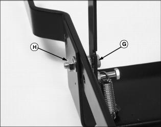
4. Install left latch lever bolt (G) through middle hole of left support rail and drawbar support frame. Install 5/16 in. flanged hex nut (H).
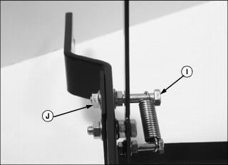
5. Install left front corner bolt (I). Install 5/16 in. flanged hex nut (J). Tighten.
6. Tighten or loosen rear bolts on each side to allow latch lever to move freely.
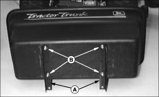
Install Trunk Box Mount Supports
NOTE: Install bolts with bolt heads inside and hex nuts outside trunk. Do not tighten bolts until trunk is installed on support frame.
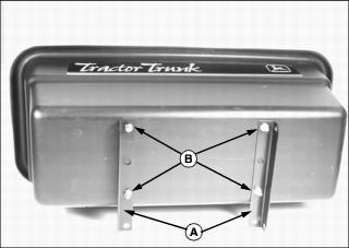
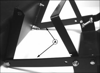
1. Place trunk on flat surface with label side up. Align two trunk box mount supports (A) so bolts go through first and third holes on supports. Top of supports should be flush with trunk.
2. Install four 5/16x1 in. box mounting bolts through trunk and trunk box mount supports (A). Install 5/16 in. flanged hex nuts (B).
Installing Mounting Bolts
NOTE: Bolt assembly can be found in bag of parts.
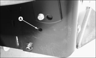
1. Locate hole (A) on left side of rear tractor frame.
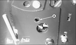
2. Locate hole (A) on right side of rear tractor frame.
3. Install M10x40 mounting bolt (B), M10 flat washer (C), and spacer (D) from outside of tractor frame. Secure bolt assembly with M10 lock washer (E) and M10 hex nut (F) on inside of frame. Tighten completely. Repeat process on other side of frame.
Attach Trunk to Support Rails/Latch Lever Assembly
1. Place trunk label-side down. Install trunk support assembly rails (A) outside trunk mount supports.
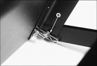
2. Install 3/8x3/4 in. drilled pin, 3/8 in. flat washer, and spring locking pin (B), on each side.
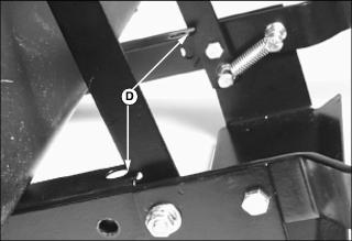
3. Pull trunk toward latch lever. Seat ends of trunk box mount supports into notches of latch lever (D).
Identify Parts (STX, LT, LX, GT Series Tractors)
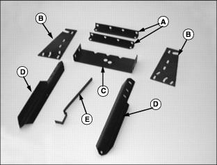
Box of Parts
Bag of Parts
Install Mounting Kit (BM19211) (STX's, LX277-AWS, 325, 345, and GT Series Tractors Only)
This Mounting Kit is used on STX, LX277-AWS, 325, 345, and GT Series Tractors only. See PREPARING VEHICLE section to install mounting kit to tractor.
Assembly (STX Model and LX Lawn Tractors Without Bagger Attachment)
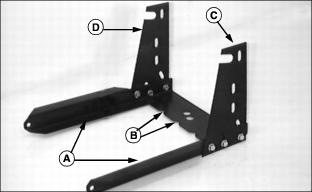
Assemble Support Frame
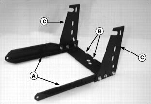
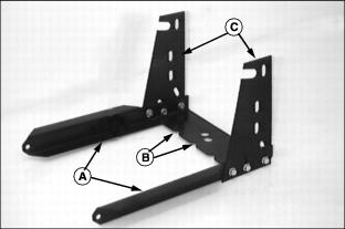
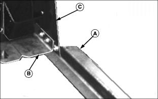
1. Position support rails (A) and vertical supports (C) outside of drawbar support.
· Notches (B) on the drawbar support must face forward.
· Vertical supports (C) are positioned outside of support rails.

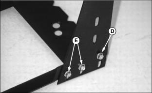
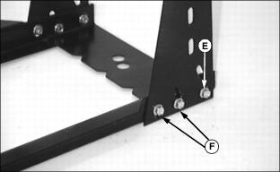
2. Install one 5/16x5/8 in. hex flanged bolt through lower, front hole (D) on each side of vertical side support. Install 5/16-18 in. nuts. Do not tighten.
3. Install two 5/16x5/8 in. hex flanged bolts and two 5/16-18 in. nuts (E) in remaining holes on each side of vertical side support. Do not tighten.
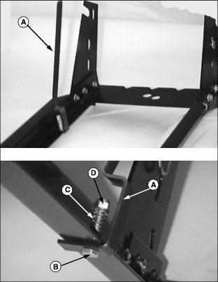
Attach Latch Lever
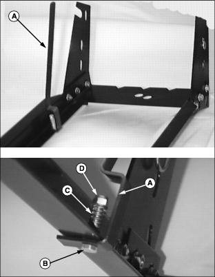
1. Install dump latch lever (A) to left side of support frame using one 1/4x1.50 in. hex head bolt (B), spring (C), and 1/4 in. lock nut (D). Turn nut onto bolt so thread is exposed.
2. Install handle cover on latch lever.
Install Trunk Box Mount Supports
NOTE: Install bolts with bolt heads inside and hex nuts outside trunk. Do not tighten bolts until trunk is installed on support frame.

Assembly (LT Lawn Tractors)
Assemble Support Frame
1. Position support rails (A) and vertical supports (C) outside of drawbar support.
· Notches (B) on drawbar support must face forward.
· Vertical supports (C) are positioned outside of support rails.
2. Install one 5/16x5/8 in. hex flanged bolt through upper, front hole (D) on each side of vertical side support. Install 5/16-18 in. nuts. Do not tighten.
3. Install two 5/16x5/8 in. hex flanged bolts and two 5/16-18 in. nuts (E) in remaining holes on each side of vertical side support. Do not tighten.
Attach Latch Lever

1. Install dump latch lever (A) to left side of support frame using one 1/4x1.50 in. hex head bolt (B), spring (C), and 1/4 in. lock nut (D). Turn nut onto bolt so thread is exposed.
2. Install handle cover on latch lever.
Install Trunk Box Mount Supports
NOTE: Install bolts with bolt heads inside and hex nuts outside trunk. Do not tighten bolts until trunk is installed on support frame.

Assembly for GT Series, 325, and 345 Lawn and Garden Tractors
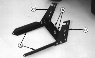
Assemble Support Frame
1. Position support rails (A) and vertical supports (C) outside of drawbar support.
· Notches (B) on drawbar support must face rearward.
· Vertical supports (C) are positioned outside of support rails.
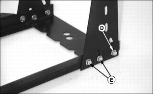
2. Install one 5/16x5/8 in. hex flanged bolt through lower, front hole (D) on each side of vertical side support. Install 5/16-18 in. nuts. Do not tighten.
3. Install two 5/16x5/8 in. hex flanged bolts and two 5/16-18 in. nuts (E) in remaining holes on each side of vertical side support. Do not tighten.
Attach Latch Lever
1. Install dump latch lever (A) to left side of support frame using one 1/4x1.50 in. hex head bolt (B), spring (C), and 1/4 in. lock nut (D). Turn nut onto bolt so thread is exposed.
2. Install handle cover on latch lever.
Install Trunk Box Mount Supports
NOTE: Install bolts with bolt heads inside and hex nuts outside trunk. Do not tighten bolts until trunk is installed on support frame.

Assembly for LX Lawn Tractors With Bagger Attachment
Assemble Support Frame
1. Position support rails (A) and vertical supports (C) to drawbar support.
· Notches (B) on drawbar support must face rearward.
· Right vertical support (C) is mounted between drawbar support (B) and support rail (A).
· Left vertical support (D) is mounted on outside of vertical support.
2. Install one 5/16x5/8 in. hex flanged bolt through lower, front hole (E) on each side of vertical side support. Install 5/16-18 in. nuts. Do not tighten.
3. Install two 5/16x5/8 in. hex flanged bolts and two 5/16-18 in. nuts (F) in remaining holes on each side of vertical side support. Do not tighten.
Attach Latch Lever

1. Install dump latch lever (A) to left side of support frame using one 1/4x1.50 in. hex head bolt (B), spring (C), and 1/4 in. lock nut (D). Turn nut onto bolt so thread is exposed.
2. Install handle cover on latch lever.
Install Trunk Box Mount Supports
NOTE: Install bolts with bolt heads inside and hex nuts outside trunk. Do not tighten bolts until trunk is installed on support frame.