![]()
Introduction
Product Identification
Safety
Operating
Replacement Parts
Service Intervals
Service Lubrication
Service Engine
Service Transmission
Service Steering
Service Mower
Replacing Primary Mower Drive Belt
Replacing Mower Deck (Secondary) Belt (42 All Purpose)
Adjusting Mower Deck Timing Belt Tension (Freedom42)
Replacing Mower Deck Secondary Belt and Timing Belt (Freedom42)
Replacing Mower Deck (Secondary) Belt (48C)
Checking for Bent Mower Blades
Servicing Mower Blades (42 All Purpose and 48C)
Servicing Mower Blades (Freedom42)
Service Electrical
Service Miscellaneous
Troubleshooting
Storage
Assembly
Specifications
Warranty
John Deere Quality Statement
Service Record

Service Mower
Removing Mower
1. Park machine safely. (See Parking Machine Safely in the Safety Section.)
2. Adjust mower cutting height to the lowest position.
Lock the lift lever in the mowing position when installing or removing the mower. |
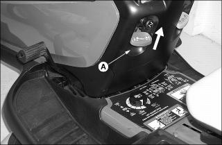
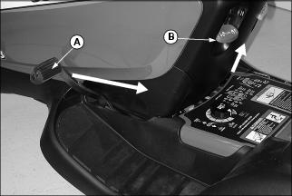
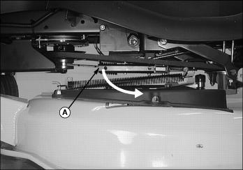
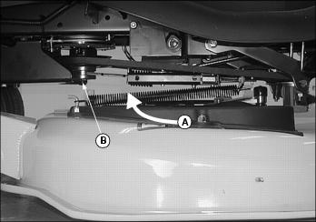
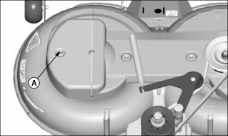
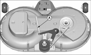
3. Lower mower to the ground and pull up on lift lever (A) to lock mower in the down position.
Hold belt tension lever securely when installing or removing drive belt. |
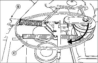
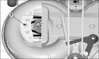
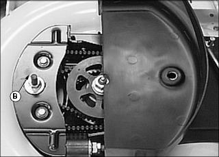
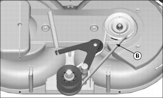
NOTE: To ease spring tension, a gripping device may be used, such as an adjustable open-end wrench, to hold the end of tensioning lever (B) when releasing belt tension.
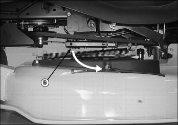
4. Hold belt tensioning lever (B) securely and slowly pull it all the way out toward you as far as it will go to release belt tension.

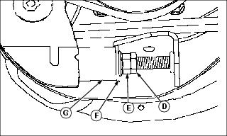
Picture Note: Mower deck shown removed from tractor for illustration.
5. Slide belt tensioning bracket forward, lift off mower sheave (C) and remove bracket.
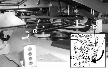
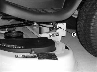
6. Hold mower sheave (C) securely and slowly move it toward front of tractor to release tension and remove drive belt (D).
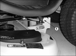
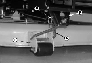
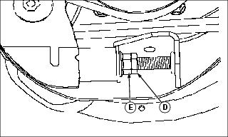
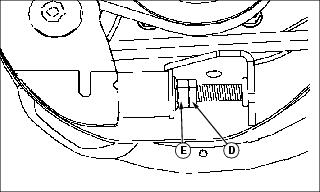
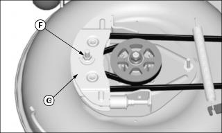
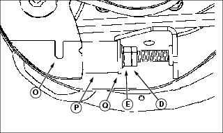
7. Check that mower lift lever is locked, remove spring locking pin and drilled pin (E) and disconnect lift arms, one on each side.
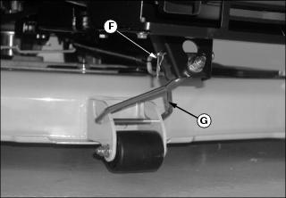
8. Remove spring locking pin and drilled pin (F) and remove front draft rod (G).
Hold lift pedal securely when releasing from lock (lower) position. |
9. Raise mower lift arms to transport position:

a. Pull back and hold attachment lift pedal (H).
b. Push attachment lift lever (I) down to unlock.
c. Hold lift pedal securely and slowly move it to the down position.
10. Slide mower deck out from under the tractor.
Installing Mower
1. Park machine safely. (See Parking Machine Safely in the Safety Section.)
2. Raise mower lift arms to transport position:
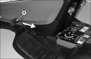
a. Pull back and hold attachment lift pedal (A).
Picture Note: When the lift pedal is down, the mower lift arms are in the up position.
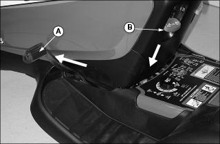
b. Push attachment lift lever (B) down to unlock.
c. Move lift pedal (A) slowly forward.
3. Adjust mower cutting height to the lowest position.
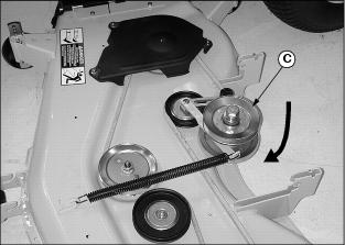
4. Move mower drive sheave (C) inward to tighten mower belt.
5. Slide mower deck under the tractor and line up mower deck lift brackets, one on each side, with lift arms.
Lock the lift lever in the mowing position when installing or removing the mower. |
a. Hold attachment lift pedal (A) securely and pull it back as far as it will go and hold.
b. Lift up on attachment lift lever (B) and lock lift arms in mowing (down) position.
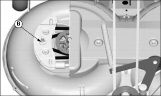
Picture Note: Put drilled pin head (D) to the outside as shown. 48C used for photo purposes.
7. Put head of drilled pin (D) to the outside as shown and install lift arms to mower lift brackets. Secure with spring locking pin to the inside.
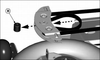
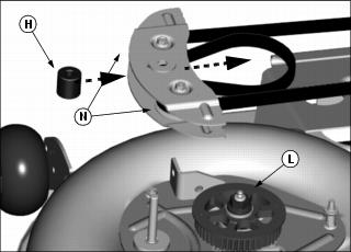
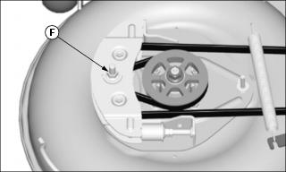
8. Slide front draft rod (E) into hole in bracket (F) in front of tractor and onto deck bracket (G).
9. Fasten with drilled pin and spring locking pin (H).
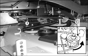
10. Put drive belt around mower sheave (C) and engine drive sheave (I) and move mower sheave back to tighten drive belt.
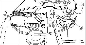
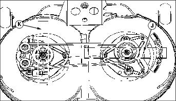
Picture Note: Mower deck shown removed from tractor for clarity.
11. Put hole end of drive belt tensioning bracket (J) over top bolt of mower sheave. Tensioning bracket should be in the open position as shown.
Hold belt tension lever securely when installing or removing drive belt. |
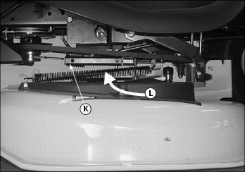
12. Put open end (K) of bracket on bottom of tractor drive sheave.
NOTE: To ease spring tension, a gripping device may be used, such as an adjustable open-end wrench, to hold the end of tensioning lever (L) when tightening belt.
13. Push tensioning bracket lever (L) in to tighten belt.
16. Adjust mower wheels for desired cutting height.
Replacing Primary Mower Drive Belt
1. Park machine safely. (See Parking Safely in the Safety Section).
2. Put mower deck in the lowest position.
Hold belt tension lever securely when installing or removing drive belt. |
NOTE: To ease spring tension, a gripping device may be used, such as an adjustable open-end wrench, to hold the end of tensioning lever (A) when releasing belt tension.
3. Hold belt tensioning lever (A) securely and slowly pull it all the way out toward you as far as it will go to release belt tension.
Hold mower sheave securely when removing and installing drive belt. |
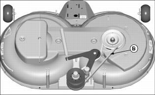
4. Remove open end of the tensioning bracket (B) from the engine drive sheave and set on top of mower deck.
5. Hold mower sheave securely and move it toward the front of the tractor to loosen belt and remove mower drive belt (C) from engine drive sheave and mower sheave.
6. Inspect belt for wear or damage; replace as necessary.
7. Place belt around mower sheave and engine sheave.

8. Push the mower sheave to the rear of the tractor and tighten belt.
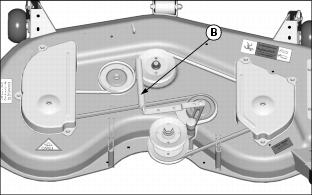
Picture Note: 48C mower deck used for photo purposes.
9. Put open end of tensioning bracket (B) on to the lower part of drive sheave.
NOTE: To ease spring tension, a gripping device may be used, such as an adjustable open-end wrench, to hold the end of tensioning lever (A) when tightening belt.
10. Push belt tensioning lever (A) in to tighten belt.
Replacing Mower Deck (Secondary) Belt (42 All Purpose)
1. Park machine safely. (See Parking Safely in the Safety Section.)
4. Disconnect idler spring (B).
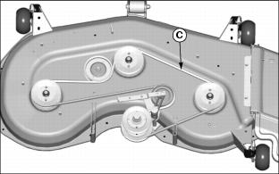
6. Inspect belt for wear or damage; replace as necessary.
7. Clean top surface of mower deck and sheaves.
8. Install belt on mower deck as shown.
9. Connect idler spring to idler arm.
Adjusting Mower Deck Timing Belt Tension (Freedom42)
IMPORTANT: Avoid damage! Damage may occur to the belt or blades after a major blade impact: |
1. Park machine safely. (See Parking Safely in the Safety Section.)
2. Put mower deck in the lowest position.
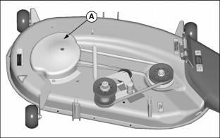
Picture Note: Mower deck removed for photo clarity only. The belt tensioning spring assembly can be accessed without removing the mower deck or the timing belt cover.
3. Remove lock nut (A) and open left spindle cover.
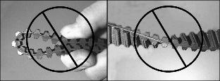
4. Check timing belt for damage. If the belt is damaged, replace the timing belt.
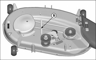
5. Remove top washer and loosen idler assembly center nut (B) one full turn. Do not remove nut.
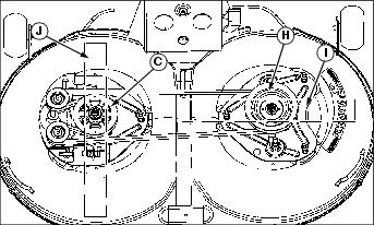
Picture Note: Underside of deck shown for illustration only.
6. Check that blades are timed (90° from each other).
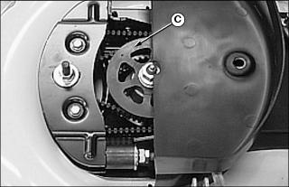
7. Turn left spindle sprocket (C) in clockwise direction to be sure belt is seated properly in the sprockets and idlers.
IMPORTANT: Avoid damage! Incorrect belt tensioning can cause belt damage. Do not over tighten belt tensioning spring assembly. |
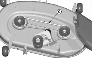
8. Loosen jam nut (D) and adjusting nut (E) so that there is a small gap between washer (F) and spring bushing (G).
9. Rotate adjusting nut (E) clockwise until the washer (F) makes solid contact with the surface of the spring bushing (G).
10. Tighten idler assembly center nut (B) to 73 N·m (54 lb-ft).
11. Tighten jam nut (D) against adjusting nut (E) to 27 N·m (20 lb-ft).
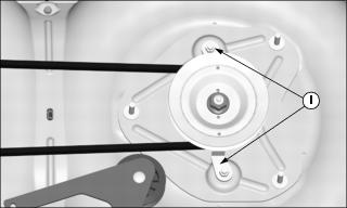
12. Turn left spindle sprocket in clockwise direction to be sure belt is seated properly in the sprockets and idlers.
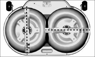
NOTE: The position of the drain holes in the spindle sheave (H) and the indentations in the timing sprocket (C) are in alignment with the mower blades (I) and (J).
13. Check that blades are timed (90° from each other).
14. Install top washer on top of center nut (B) and close left spindle cover.
15. Fasten cover with lock nut and tighten to 14 N·m (10 lb-ft).
Replacing Mower Deck Secondary Belt and Timing Belt (Freedom42)
1. Park machine safely. (See Parking Safely in the Safety Section.)
2. Remove mower deck from tractor.
3. Check blade bolt torque. Carefully hold blade with glove, use a hand torque wrench, and tighten bolt to 62 N·m (46 lb-ft).
4. Disconnect idler spring (A).
5. Remove secondary belt (B) from right spindle sheave.

6. Remove five nuts (C) and remove cover.
7. Turn jam nut (D) and adjusting nut (E) counterclockwise to end of threaded rod, and remove tensioning spring assembly.
8. Remove center nut and washer (F) and remove fixed idler assembly (G) from left support plate. Do not loosen other idler assembly hardware that retains idlers.
9. Remove spacer (H) located between fixed idler assembly plates and remove idler assembly from belt.
10. Loosen two belt guides (I) and rotate away from left sprocket.
11. Remove damaged timing belt.
12. Clean top surface of mower deck and sheaves.
NOTE: The position of the drain holes in the spindle sheave (A) and the indentations in the timing sprocket (L) are in alignment with the mower blades (J) and (K).
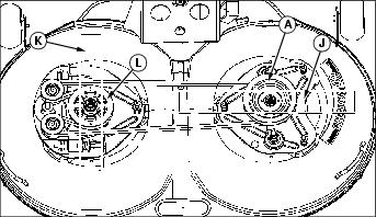
13. Position mower blades (J) and (K) 90° from each other.
14. Install new mower deck timing belt.
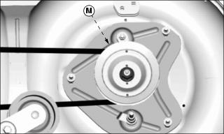
a. Route belt around right spindle sprocket (M) located under the mower drive belt sheave.
b. Route belt around outside of idlers and then in between left fixed idlers (N) pulling a belt loop through the idler assembly.
c. Insert spacer (H) between fixed idler plates and idlers.
d. Install the fixed idler assembly on the stud of the left support plate.
e. Wrap belt loop around left spindle sprocket (L).
15. Install washer and center nut (F) on fixed idler assembly. Leave nut one turn loose at this time.
16. Check that blades (J) and (K) are still timed (90° from each other).
IMPORTANT: Avoid damage! Incorrect belt tensioning can cause belt damage. DO NOT over tighten belt tensioning spring assembly. |
17. Install tensioning spring assembly and adjust timing belt tension.
a. Align notch (O) in idler assembly with tab on spring bushing (P).
b. Rotate adjusting nut (E) clockwise until the washer (Q) makes solid contact with the surface of the spring bushing (P).
c. Turn adjusting nut an additional 1/2 turn to allow for new belt stretch. Do not over tighten.
d. Turn right spindle sheave several rotations clockwise and observe that belt is riding properly in sprockets and idlers.
e. Tighten jam nut (D) against adjusting nut.

18. Tighten center nut (F) to 73 N·m (54 lb-ft).
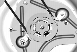
IMPORTANT: Avoid damage! Check belt guide-to-sprocket rim clearance. Measuring clearance incorrectly can cause belt or blade damage. |
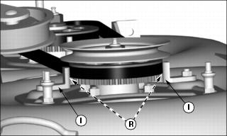
a. Hold a 1 mm (0.039 in.) shim/gage between belt guides and sprocket rim, location (R), and rotate belt guides (I) clockwise against gage.
b. Tighten belt guide nuts to 24 N·m (18 lb-ft).
Picture Note: Right spindle sheave removed for photo clarity only.
c. Remove gage and inspect belt guide-to-sprocket rim clearance (R) while rotating spindle in the clockwise direction. Clearance (R), one on each side, should be 1 0.5 mm (0.039 0.020 in.). Belt should not contact belt guide.
20. Install timing belt cover.
21. Install secondary belt (B) on right spindle as shown.
Replacing Mower Deck (Secondary) Belt (48C)
1. Park machine safely. (See Parking Safely in the Safety Section.)

3. Remove two belt shields (A).
4. Disconnect idler spring (B).
6. Inspect belt for wear or damage; replace as necessary.
7. Clean top surface of mower deck and sheaves.
8. Install belt on mower deck as shown.
9. Connect idler spring to idler arm.
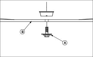
Checking for Bent Mower Blades
1. Park machine safely. (See Parking Safely in the Safety Section.)
2. Lower mower deck to mowing position.
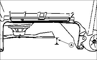
Picture Note: Mower deck with side discharge used for illustration.
3. Measure distance (A) between blade tip and flat ground surface.
4. Turn blade. Measure distance between other blade tip and flat ground surface.
5. Install new blade if the difference between the two measurements is more than 3 mm (1/8 in.).
Servicing Mower Blades (42 All Purpose and 48C)
Removing Mower Blades
1. Raise mower deck to gain access to mower blades. If necessary, remove mower deck.
2. Block mower blade with a piece of wood to prevent it from spinning.
3. Loosen and remove bolt (A), washer (B) and blade (C).
4. Inspect blades; sharpen, balance or replace blades as necessary.
Installing Mower Blades
1. Make sure deflector cups (D) are in place between spindle and blade.
2. Position mower blades (C) with the cutting edge towards the ground onto the mower spindle.
3. Install blade washer (B) with cup side toward the blade.
4. Install and tighten bolt (A) by hand until mower blade is in full contact (fully seated) with spindle.
5. Block mower blade with a piece of wood to prevent spinning and tighten bolts to:
· 42 All Purpose Mower Deck: 75 N·m (55 lb-ft).
· 48C Mower Deck: 68 N·m (50 lb-ft).
Servicing Mower Blades (Freedom42)
Removing Mower Blades
1. Hold mower blade with glove to prevent mower blades from spinning.
2. Raise mower deck to gain access to mower blades. If necessary, remove mower deck.

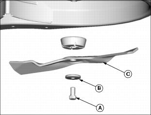
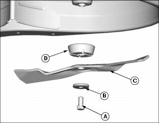
3. Loosen and remove bolt with washer (A), and blade (B).
4. Inspect blades; sharpen, balance or replace blades as necessary.
Installing Mower Blades
1. Check mower to be sure you are installing the blades on the correct side.
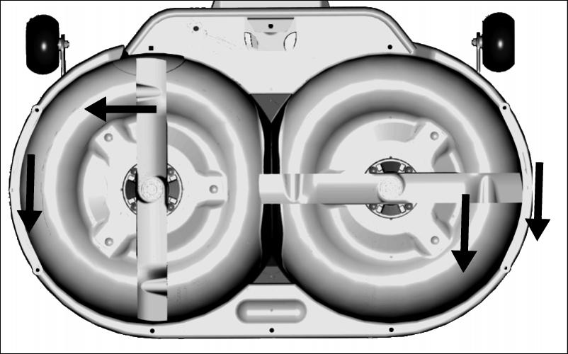
· There are direction arrows located on each outside edge of the mower. There is a right and a left side blade. The blades are marked for identification.
2. Position mower blades (B) with the cutting edge towards the ground onto the mower spindle and align key on bottom of spindle with slot in blade.
3. Install and hand tighten bolt with washer (A) until mower blade is in full contact (fully seated) with spindle.
4. Hold mower blade with glove to prevent spinning, tighten bolts to 62 N·m (46 lb-ft).
5. Check mower deck timing and adjust if necessary.
Sharpening Blades
· Sharpen blades with grinder, hand file, or electric blade sharpener.
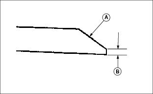
· Keep original bevel (A) when grinding.
· Blade should have 0.40 mm (1/64 in.) cutting edge (B) or less.
· Balance blades before installing.
Balancing Blades
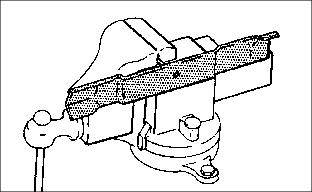
2. Put blade on nail in a vise. Turn blade to horizontal position.
3. Check balance. If blade is not balanced, heavy end of blade will drop.