![]()
Introduction
Product Identification
Safety
Operating
Avoid Damage to Plastic and Painted Surfaces
Adjusting Mower Deck Wheels (42 All Purpose)
Adjusting Mower Deck Wheels (Freedom42)
Adjusting Mower Deck Wheels (48C)
Adjusting Mower Level (Side-to-Side)
Adjusting Mower Level (Front-to-Rear)
Testing Reverse Implement Option (RIO)
Using Indicator Lights and Hour Meter (SST18)
Using Reverse Implement Option
Pushing Machine (Using Free-Wheeling Lever)
Unplugging Mower or Optional Bagger
Transporting Machine on Trailer
Replacement Parts
Service Intervals
Service Lubrication
Service Engine
Service Transmission
Service Steering
Service Mower
Service Electrical
Service Miscellaneous
Troubleshooting
Storage
Assembly
Specifications
Warranty
John Deere Quality Statement
Service Record

Operating
Daily Operating Checklist
o Check transmission oil level.
o Remove grass and debris from machine.
o Clean area around transmission and steering switches.
o Check area below machine for leaks.
Avoid Damage to Plastic and Painted Surfaces
· Do not wipe plastic parts unless rinsed first.
· Insect repellent spray may damage plastic and painted surfaces. Do not spray insect repellent near machine.
· Be careful not to spill fuel on machine. Fuel may damage surface. Wipe up spilled fuel immediately.
Operator Station Controls

Picture Note: Model SST18 shown
B - Engine Oil Pressure Light (SST18 Only)
C - Battery Discharge Light (SST18 Only)
E - PTO Switch/Reverse Implement Option (RIO) Switch
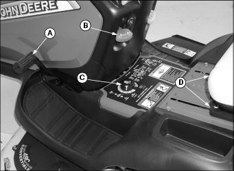
B - Attachment Lift Lock Lever
Miscellaneous Controls
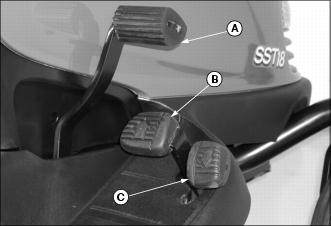
Adjusting Seat
To adjust seat position:
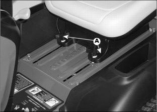
2. Slide seat forward or rearward to desired position.
To adjust seat for ride comfort:
Lift seat and move springs to desired position as follows:
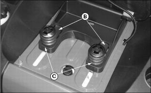
· Install both springs into front position (B) for softest ride.
· Install both springs into rear position (C) for firm ride.
· Install springs in all four positions (B and C) for the firmest ride. (Order additional springs from your John Deere dealer.)
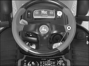
Adjusting Cutting Height
Cutting height can be adjusted from approximately 25-100 mm (1-4 in). When mower deck is in transport position, cutting height is approximately 100 mm (4 in).
2. Raise mower deck to highest position.
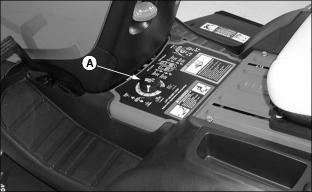
3. Turn cutting height knob (A) to desired cutting height. Mower will be at that approximate cutting height when it is lowered.
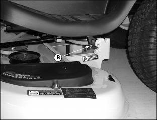
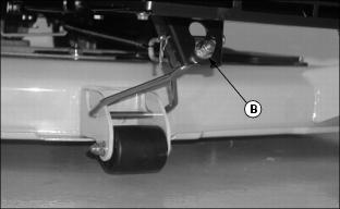
4. Check that the actual height of cut matches the reading on the cutting height knob. if they do not match, adjust lift links (B) on both sides of mower.
· Turn nuts (B) clockwise to raise the mower deck to match the cutting height knob.
· Turn nuts (B) counterclockwise to lower the mower deck to match the cutting height knob.
5. Check side-to-side mower level.
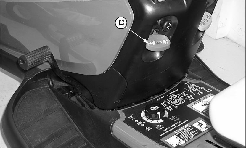
7. Raise mower deck to the transport position and lock lift lever (C). If lift lever does not lock, lower the mower deck.
a. Turn nuts (B), one on each side, one turn counterclockwise to lower the mower deck.
b. Check that lift lever locks when mower deck is in the transport position.
c. Repeat until lift lever locks in transport.
Adjusting Mower Deck Wheels (42 All Purpose)
1. Park machine safely. (See Parking Safely in the Service section.)
2. Inflate tires to the correct pressure.
3. Raise mower deck to the transport position and adjust cutting height.
4. Lower mower deck to the desired mowing position.
NOTE: Bottom of wheels should be approximately 3-13 mm (1/8-1/2 in.) from the ground.
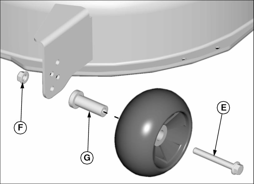
5. Check mower wheel position. Remove bolt (E) and nut (F) on all wheels and move wheels with bushing (G) to proper hole.
6. Install bolts and nuts to lock wheels in position. Tighten nuts to 34 N·m (25 lb-ft).
Adjusting Mower Deck Wheels (Freedom42)
1. Park machine safely. (See Parking Safely in the Service section.)
2. Inflate tires to the correct pressure.
3. Raise mower deck to the transport position and adjust cutting height.
4. Lower mower deck to the desired mowing position.
NOTE: Bottom of wheels should be approximately 3-13 mm (1/8-1/2 in.) from the ground.
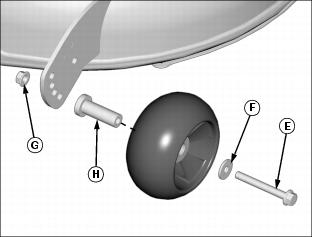
5. Check mower wheel position. Remove bolt (E), washer (F), and nut (G) on all wheels and move wheels with bushing (H) to proper hole.
6. Install bolts, washers and nuts to lock wheels in position. Tighten nuts to 34 N·m (25 lb-ft).
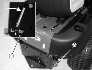
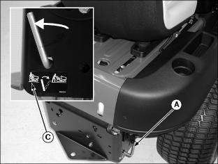
Adjusting Mower Deck Wheels (48C)
1. Park machine safely. (See Parking Safely in the Service section.)
2. Inflate tires to the correct pressure.
3. Raise mower deck to the transport position and adjust cutting height.
4. Lower mower deck to the desired mowing position.
NOTE: Bottom of wheels should be approximately 3-13 mm (1/8-1/2 in.) from the ground.
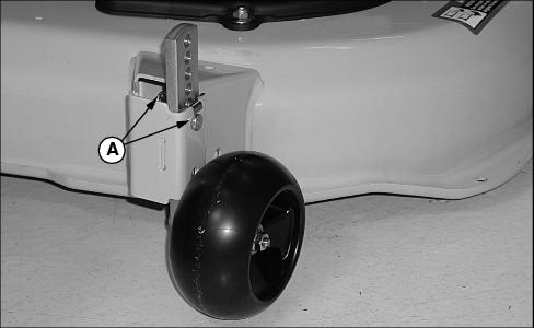
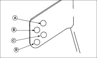
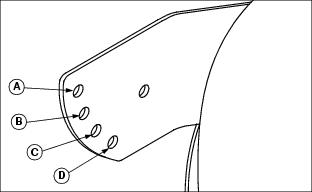
5. Check mower wheel position. Remove spring locking pin and drilled pin (A) on all wheels.
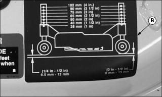
6. Use decal (B) located on top of deck and move wheels to proper hole.
7. Install spring locking pins and drilled pins to lock wheels in position.
Adjusting Mower Level (Side-to-Side)
NOTE: Mower wheels should not contact the ground when leveling the deck.
1. Park machine safely. (See Parking Safely in the Safety Section.)
2. Inflate tires to the correct pressure.
3. Adjust cutting height to 50 mm (2 in.).
NOTE: The difference between blade measurements must not be more than 3 mm (1/8 in.).
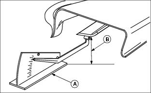
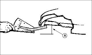
Picture Note: A convenient leveling gauge (A) (AM130907) is available from your John Deere dealer.
5. Position mower blades as follows and measure from each outside blade tip (B) to the level surface:
Picture Note: 42 All Purpose used for illustration
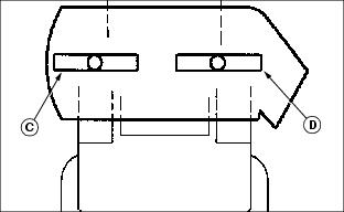
· 42 All Purpose and 48C mowers:
Turn left blade (C) as shown. Hold drive belt and turn right blade (D) as shown. Take measurement for both blades.
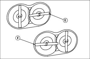
Picture Note: Underside of Freedom42 deck shown.
· On Freedom42 mulching mower:
Turn blade (E) as shown. Take measurement. Rotate blades 90° so that blade (F) is positioned as shown. Take measurement.
NOTE: Cutting height can closely match knob setting by adjusting lift links on both sides of deck.
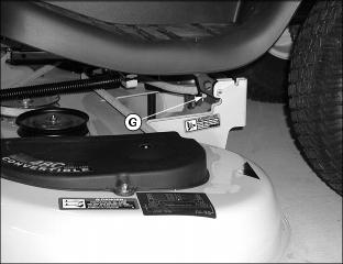
Picture Note: Left side of 48C shown.
6. Adjust lift links by turning nut (G) clockwise to raise left side of mower, counterclockwise to lower left side of mower.
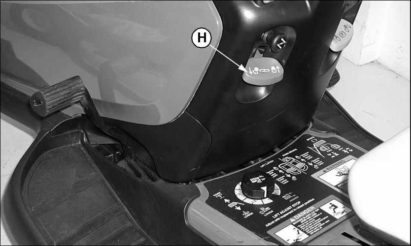
7. Raise mower deck to the transport position and lock lift lever (H). If lift lever does not lock, lower the mower deck.
a. Turn nut (G) one turn counterclockwise to lower the mower deck.
b. Check that lift lever locks when mower deck is in the transport position.
c. Repeat until lift lever locks in transport.
Adjusting Mower Level (Front-to-Rear)
NOTE: Mower wheels should not contact the ground during leveling.
1. Park machine safely. (See Parking Safely in the Safety Section.)
2. Inflate tires to the correct pressure.
3. Adjust cutting height to 50 mm (2 in.).
5. Turn right blade so blade tip points straight forward.
Picture Note: A convenient leveling gauge (AM130907) is available from your John Deere dealer.
6. Measure from each blade tip to the surface, distance (A):
· 42 All Purpose and 48C decks:
The front blade tip must be 6-9 mm (1/4-3/8 in.) lower than rear blade tip.
The difference between front and rear blade tip measurements must not be more than 3 mm (1/8 in.).
7. Turn front adjuster nut (B) clockwise to raise front of mower deck or counterclockwise to lower front of mower deck.
8. Measure blade tips again and adjust if necessary.
Testing Safety Systems

Use the following checkout procedure to check for normal operation of machine.
If there is a malfunction during one of these procedures, Do not operate machine. See your John Deere dealer for service.
Perform these tests in a clear open area. Keep bystanders away.
Testing Park Brake Switch
1. Park machine safely. (See Parking Safely in the Safety Section.)

Testing Park Brake
1. Park machine safely. (See Parking Safely in the Safety Section.)
3. Engage free-wheeling lever.
4. Try to push machine manually.
Testing PTO Switch
1. Park machine safely. (See Parking Safely in the Safety Section.)
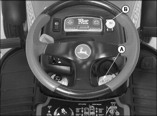
4. Pull PTO switch (B) up to engage.
Testing Seat Switch
1. Park machine safely. (See Parking Safely in the Safety Section.)
b. Move throttle lever (A) up to maximum engine speed.
c. Unlock park brake and release brake pedal (B).
e. Raise up off seat. Do not get off tractor.

c. Unlock park brake and release brake pedal (B).
d. Raise up off seat. Do not get off tractor.
d. Raise up off seat. Do not get off tractor.
Testing Belt Drive System
1. Park machine safely. (See Parking Safely in the Safety Section.)
3. Make sure that the park brake (A) is locked.
4. Push lightly on forward travel pedal (B) while turning the steering wheel to the left, and then to the right.
Testing Steering Switch
1. Park machine safely. (See Parking Safely in the Safety Section.)
3. Unlock park brake (A) and release brake pedal (B).
4. Slowly drive forward a few inches and then take foot off of forward travel pedal.
5. Turn the steering wheel to the left, and then to the right.
6. Slowly drive in reverse a few inches and then take foot off of reverse travel pedal.
7. Turn the steering wheel to the left, and then to the right.
Testing Reverse Implement Option (RIO)
Before backing up, carefully check the area around the machine. |
1. Park machine safely. (See Parking Safely in the Safety Section.)
3. Engage PTO to start attachment.
4. Look behind the vehicle to be sure there are no bystanders.
5. Begin reverse travel by depressing reverse foot pedal.
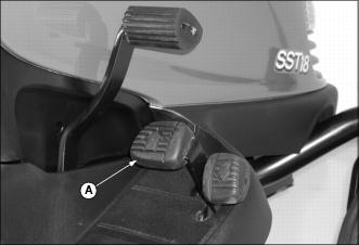
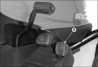
Using Park Brake
Always lock the park brake and remove the key before leaving the machine unattended. |
Locking park brake:
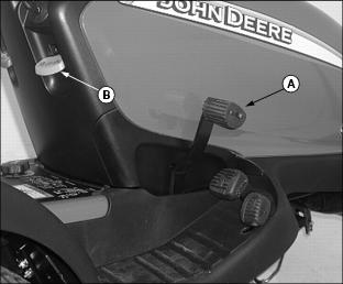
1. Push and hold brake pedal (A) down.
2. Pull park brake lever (B) up to lock park brake.
3. Release brake pedal. Pedal should stay down and park brake lever should stay locked.
Unlocking park brake:
1. Push and hold brake pedal down.
2. Push park brake lever down to unlock park brake.
Using Headlights
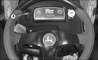
· Push top of light switch (A) down to turn headlights on.
· Push bottom of light switch to turn headlights off.
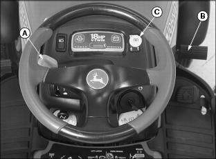
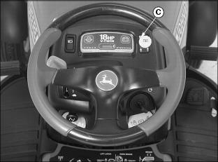
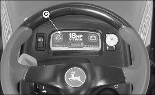
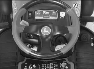
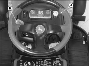
Using Indicator Lights and Hour Meter (SST18)
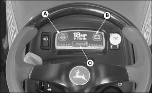
Picture Note: Model SST18 only
· Oil Pressure Indicator Ligh(A) will come on when you turn the key to the run position. Indicator light should go out within 5 seconds after engine starts. If indicator comes on during operation, engine oil pressure is too low. Stop engine and perform appropriate service.
· Battery Discharge Indicator Ligh(B) will come on when battery voltage falls below 12.3 volts. Indicator light will be on during start-up and should go out within 10 seconds. Indicator light may also remain on at low idle. If battery is at a low state of charge, indicator light may remain on when PTO and headlights are on.
· The Hour Meter (C) shows the number of hours the vehicle has run. The service chart gives necessary service intervals. Use the hour meter and the service interval section to determine when the vehicle will need service.
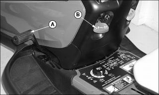
Using Fuel Gauge
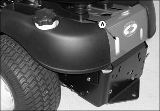
Fuel level is indicated by lines molded into fuel tank (A) at rear of tractor.
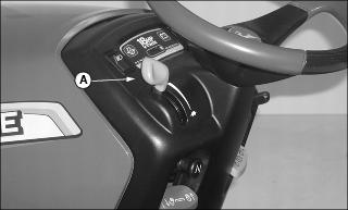
Starting the Engine
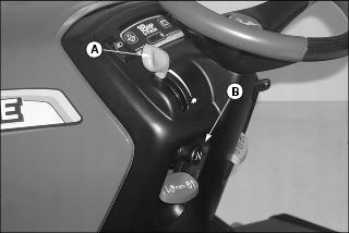
Move throttle lever (A) to the half-speed position and pull out choke knob (B). Gradually push in the choke knob after the engine starts.
Move throttle lever (A) to the half-speed position.
Picture Note: Model SST18 only
3. On SST18: Turn key to run position and check indicator lights. Oil Pressure indicator light (C) will come on.
IMPORTANT: Avoid damage! Starter may be damaged if starter is operated for more than 20 seconds at a time: · Wait two minutes before trying again if engine does not start. |
NOTE: The following procedure will improve starting and will reduce the chance of flooding and muffler backfire.
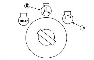
4. Turn key to start position (D) for no more than five seconds.
5. Release key to the run position (E) when engine starts:
· If engine does not start, wait 10 seconds.
· Turn key to start position again for no longer than 5 seconds.
· Repeat procedure if necessary.
IMPORTANT: Avoid damage! Unnecessary engine idling may cause engine damage. Excessive idling can cause engine overheating, carbon build-up, and poor performance. |
6. Let engine run at half-speed position for a couple of minutes to warm-up before operating machine.
Stopping the Engine
1. Move throttle lever (A) to slow position and let engine run at low throttle a few seconds.
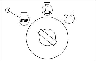
2. Turn key to STOP position (B).
Emergency Stopping
Push brake pedal (A) to stop machine and steering.
Driving the Machine
Always practice driving the Spin-Steer before you begin mowing. Keep practicing until you feel confident in your maneuvering and driving skills.
Unlike traditional tractors, the rear wheels on the machine do all of the steering. The front wheels are caster wheels and are not controlled by the steering wheel. At startup, remember if you do not turn the steering wheel the tractor will go straight.
Turning: Using Spin-Steer Technology (Zero Turn Radius)
Pushing the forward and reverse pedals activates steering.
Changing ground speed affects the turning radius.
· The turn becomes tighter as speed is reduced.
· The turn becomes wider as speed is increased.
The best way to execute a turn is to:
2. Turn the steering wheel to a full turn.
4. Resume travel speed and guide the steering wheel to a straight-ahead position.
To travel forward:
1. Push down the forward travel pedal (A) slowly and guide the steering wheel straight-ahead as you begin travel.
2. Push down the forward travel pedal until the desired travel speed is obtained.
To travel in reverse:
NOTE: The engine and attachment will stop as the reverse pedal is pushed if the PTO knob is not in the off position.
1. Push PTO knob down to the off position to disengage attachment.
2. Look behind the machine to be sure there are no bystanders nearby.
3. Push down the reverse travel pedal (B).
To stop travel and steering:

Using Reverse Implement Option
Before backing up, carefully check the area around the machine. |
NOTE: Operating the mower while backing up is strongly discouraged. The Reverse Implement Option should be used only when operating another attachment or when the operator deems it necessary to reposition the machine with the mower engaged.
2. Look behind the vehicle to be sure there are no bystanders.
3. Lift and hold the PTO knob (A) up past the PTO engagement position while depressing reverse foot pedal slightly.
NOTE: If the engine and attachment stop while repositioning the machine, return PTO knob to the off position. Start engine and engage attachment. Begin again with Step 2.
4. As the machine begins to move rearward, release the PTO knob and reposition the machine.
5. Resume forward travel. The attachment should continue operating.
6. Repeat procedure to position the machine again.
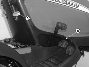
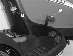
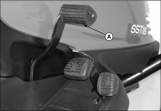
Using Mower Lift Pedal
Raising Mower Deck:
1. Push and hold lift pedal (A) down.
2. Pull lift lever (B) up to lock mower deck in the transport position.
3. Release lift pedal. Pedal should stay down and lift lever should stay locked.
Lowering Mower Deck:

1. Push and hold lift pedal (A) down.
2. Push lift lever (B) down to unlock.
3. Release lift pedal. Mower deck will be lowered to the set cutting height.
Using Mower
1. Start engine and run at half-speed position for a couple of minutes to warm-up.
2. Lower mower to desired cutting height position.
3. Pull PTO knob (A) up to start mower.
4. Push throttle lever (B) up to the full throttle position.
NOTE: The mower and engine will stop as the reverse foot pedal is depressed with mower engaged.
5. Disengage PTO before moving in reverse.
6. Push PTO knob (A) down to stop mower blades.
Mower Blade Selection
42 All Purpose Blades:
· Standard Blades: Designed for bagging, side discharging and mulching.
IMPORTANT: Avoid damage! Blades that are not specifically used for mulching, will destroy the mulch plug. High lift blades must be used with the mulch plug insert. |
· High Lift Blades: Designed for cutting and bagging thick, tall grass and/or leaves.
Freedom42 Blades:
· Mower deck performance depends on using the correct mower blade for your mower. Use the following recommendation when choosing blades:
· Mulch blades are standard. (Blades must be ordered in a set, with a left and right blade.)
48C Blades:
· Standard Blades: Designed for bagging, side discharging and all mowing conditions.
· Mulching Blades: Should be used with the Optional Mulch Kit.
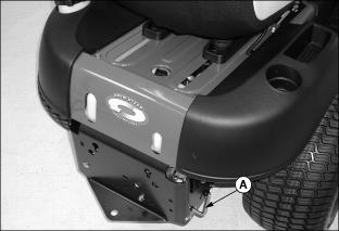
Pushing Machine (Using Free-Wheeling Lever)
IMPORTANT: Avoid damage! Transmission damage may occur if the machine is moved or towed incorrectly: |
2. Push free-wheeling lever (A) all the way forward as far as it will go until it locks in the `push' position (B).
3. Push machine to desired location.
4. Move free-wheeling lever (A) all the way back to the operating position (C).
Unplugging Mower or Optional Bagger
· Park the machine safely and lock the park brake before getting off the seat. |
3. Move throttle lever to slow position.
8. Wait for all moving parts to stop.
Transporting Machine on Trailer
Be sure trailer has all the necessary lights and signs required by law.
· Park trailer on a level surface. · Use of a trailer with sides is recommended. |
IMPORTANT: Avoid damage! Transmission damage may occur if the machine is moved or towed incorrectly: |
1. Park trailer on a level surface.
2. Drive forward onto heavy-duty trailer with sides.
3. Lower mower to trailer deck.
5. Fasten lawn tractor to trailer with heavy-duty straps, chains, or cables. Both front and rear straps must be directed down and outward from tractor.
Using Weights
NOTE: See your John Deere dealer for Front Weight Kit and Rear Wheel Weights.
· Install front weights for added stability when using equipment such as the rear-mounted grass bagger.
· Install rear wheel weights when using the snow blade and to improve slope operation.
· Remove wheel weights when not required.
Installing Tire Chains
NOTE: Chains for the rear tires are available from your John Deere dealer.
Mowing Tips
The following recommendations will produce the best lawn cut quality and appearance:
· Keep mower blades sharp. Dull blades will tear grass; tips of grass will then turn brown.
· Cutting grass too short may kill grass and let weeds grow easily. The suggested finished cut height range is 44 to 70 mm (1.75 to 2.75 in.).
· Adjust cutting height to remove only 1/3 of the grass at a time.
· Mow grass often. Short grass clippings will decay quickly.
· Mow with engine at full throttle.
· Adjust travel speed to match mowing conditions:
· Travel at SLOW speed when you mow thick, tall grass, make sharp turns, trim around objects, or when mulching.
· Travel at MODERATE speed when you mow thin grass.
· Use a different mowing pattern each time you mow. Overlap mowing paths 50 to 100 mm (2 to 4 in.).
· To allow for better cut quality mow a straight path and then SLOW the machine down to make a tight turn.
· Drive over ridges and through shallow ditches straight-on, not at an angle.
· When mulching near pavement, overlap the pavement by 50 mm (2 in.) to allow clippings to dispense over grass.
· A thick layer of mulched leaves can prevent sunlight from getting to grass and smother it. Taller grass heights allow mulched leaves to dispense easier in lawn. Mulch leaves several times if needed.
· Use a thatcher in late spring or summer to pull up dead grass and aerate ground.