![]()
Introduction
Product Identification
Safety
Operating
Replacement Parts
Service Intervals
Service Lubrication
Service Engine
Service Transmission
Service Steering
Service Mower
Service Electrical
Service Miscellaneous
Troubleshooting
Storage
Assembly
Move Mower Wheels To Mowing Position (48C)
Install Plastic Discharge Chute (48C)
Specifications
Warranty
John Deere Quality Statement
Service Record

Assembly
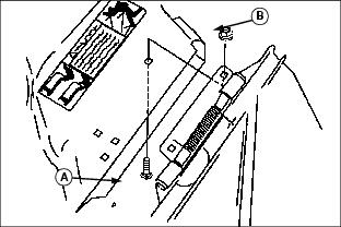
Install Steering Wheel
1. Put John Deere Multi-Purpose lubricant or an equivalent on the steering shaft.
2. Install steering wheel with John Deere logo in the upright position.

3. Install shoulder bolt (A). Drive bolt in until head of bolt contacts steering wheel.
4. Install washer and nut (B).
5. Tighten lock nut until it is snug. Do not pull washer or head of bolt into steering wheel.
Charge and Connect Battery
· Wear eye protection and gloves. · Do not allow direct metal contact across battery posts. |
· Battery is fully charged at 12.6 volts.
2. Remove and discard the RED positive (+) protective cap from the positive (+) battery terminal.

3. Connect positive (+) battery cable (A) to battery.
4. Connect negative (-) battery cable (B).
5. Apply general purpose grease or silicone spray to terminal to help prevent corrosion.
6. Slide red cover over positive battery cable.
7. Install black rubber strap (C).
Check Engine Oil Level

1. Remove dipstick (A) and wipe off with a clean cloth.
2. Install and tighten dipstick.
4. Check oil level on dipstick. Oil must be between ADD and FULL marks.
5. If oil level is low, add oil to bring oil level no higher than FULL mark on dipstick.
6. Install and tighten dipstick.
Move Mower Wheels To Mowing Position (48C)
1. Remove spring locking pins and drilled pins from three mower wheels and remove wheels from the shipping position.

2. Install three mower wheels in the mowing position and fasten to mower brackets with drilled pins and spring locking pins (A).
3. Adjust mower level before operation.
Install Plastic Discharge Chute (48C)
NOTE: Attaching hardware is installed in mower deck for shipping.
1. Install discharge chute to mower deck with two M8 x 16 bolts (A) and lock nuts (B).
2. Tighten nuts to 20 N·m (15 lb-ft).
Check Tire Pressure
2. Check tire pressure with an accurate gauge.
3. Check that tires have equal air pressure. Add or remove air, if necessary.
Level Mower Deck
Level mower deck. (See Adjusting Mower Level (Side-to-Side) and Adjusting Mower Level (Front-to-Rear) in the OPERATING section.)