![]()
Introduction
Product Identification
Safety
Operating
Replacement Parts
Service Intervals
Service Lubrication
Service Engine - Models GX325 and GX335
Service Engine - Model GX345
Service Transmission
Service Steering
Service Mower
Service Electrical
Checking Battery Electrolyte Level
Removing and Installing the Battery
Cleaning Battery and Terminals
Replacing Indicator Light Bulb
Service Miscellaneous
Troubleshooting
Storage
Assembly
Specifications
Warranty
John Deere Quality Statement
Service Record

Service Electrical
Battery Statement
Service the Battery Safely

Checking Battery Electrolyte Level
1. Park machine safely. (See Parking Safely in the SAFETY section.)
3. Remove manifold caps on top of battery.
IMPORTANT: Avoid damage! Acid may leak from the battery while it is charging. Make sure the battery is filled correctly. |
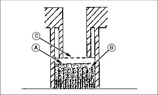
4. Check electrolyte level. Electrolyte level (A) should be 6 mm (1/4 in.) above plates (B) and below filler neck (C).
5. Add distilled water if necessary.
7. Check battery cable hardware and tighten if necessary.
Removing and Installing the Battery
Removing
1. Park machine safely. (See Parking Safely in the SAFETY section.)
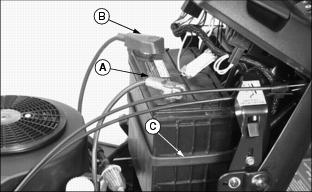
3. Disconnect negative (-) battery cable (A).
4. Push red cover (B) away from positive (+) battery terminal and remove cable from battery.
Installing
IMPORTANT: Avoid damage! Follow instructions carefully. Battery and battery cables must be installed correctly. When installing battery, make sure battery posts are facing toward front of machine. |
1. Place battery on battery tray so battery posts are facing toward front of machine.
IMPORTANT: Avoid damage! To prevent damage to fuel line on models GX325 and GX335, route positive (+) battery cable so it is not between fuel line and engine. |
2. Connect positive (+) battery cable.
3. Connect negative (-) battery cable.
4. Apply general purpose grease or silicone spray to terminals to help prevent corrosion.
5. Slide red cover over positive battery terminal.
6. Secure black rubber strap (C).
Cleaning Battery and Terminals
1. Park machine safely. (See Parking Safely in the SAFETY section.)
3. Wash battery with solution of four tablespoons of baking soda to one gallon of water. Be careful not to get the soda solution into the cells.
4. Rinse the battery with plain water and dry.
5. Clean terminals and battery cable ends with wire brush until bright.
6. Apply petroleum jelly or silicone spray to terminal to prevent corrosion.
Using Booster Battery

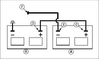
1. Connect positive (+) booster cable to booster battery (A) positive (+) post (C).
2. Connect the other end of positive (+) booster cable to the disabled vehicle battery (B) positive (+) post (D).
3. Connect negative (-) booster cable to booster battery negative (-) post (E).
4. Connect the other end (F) of negative (-) booster cable to a metal part of the disabled machine frame away from battery.
5. Start the engine of the disabled machine and run machine for several minutes.
6. Carefully disconnect the booster cables in the exact reverse order: negative cable first and then the positive cable.
Replacing Fuses
1. Park machine safely. (See Parking Safely in the SAFETY section.)

3. Pull defective starter fuse (A) or headlight fuse (B) out of socket.
4. Check metal clip in fuse window and discard fuse if clip is broken.
5. Push new 15 Amp fuse into socket.
Replacing Headlight Bulb
1. Park machine safely. (See Parking Safely in the SAFETY section.)
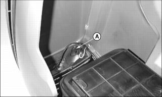
3. Turn bulb socket (A) 1/8 turn to the left to remove socket from headlight housing.
4. Push bulb down and turn 1/4 to the left to remove bulb from the socket.
5. Replace defective bulb with new bulb.
6. Insert bulb socket into housing, push in and turn 1/4 turn clockwise to install.
Replacing Indicator Light Bulb

Picture Note: Model GX345 shown.
1. Rotate indicator bulb socket 1/8 turn counterclockwise to remove:
· Oil pressure indicator light (A).
· Battery discharge light (B).
· Model GX345 Only - Coolant temperature light (C).
4. Install socket into holder and rotate 1/8 turn clockwise to secure.