![]()
Introduction
Product Identification
Safety
Preparing Vehicle
Installing
Installing Belt On Double Sheave
Removing
Operating
Replacement Parts
Service
Storage
John Deere Quality Statement
Copyright© Deere & Company

Installing
Park Vehicle Safely
· Stop vehicle on a level surface, not on a slope.
· Before you leave the operator's seat, wait for engine and all moving parts to STOP.
Installing POWER FLOW
IMPORTANT: Avoid damage! When POWER FLOW is removed from the mower, any original hardware for the discharge chute MUST be installed to prevent discharge chute from lifting up during mowing. |
NOTE: The mower should be installed before installing the POWER FLOW unit. See your mower operator manual to install mower.

1. If not removed, remove and save hardware (B) on each side of chute TO ALLOW CHUTE TO LIFT UP.
2. Pick up blower assembly by chute guard handle (A) and support tube (F). Slide support tube bushing (C) over front mounting bracket pin.
3. Swing blower into deck opening.
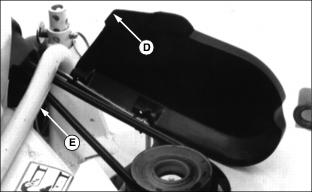
4. Place loop of POWER FLOW belt between mower and rear support tube (D).
NOTE: Front cover on POWER FLOW is open for photo clarity ONLY.

5. Latch blower against mower and into slot in deck (E).
Installing Belt On Double Sheave

1. Lift up plastic belt shield (A). Install belt on double sheave (belt MUST be crossed as shown (B)).
· Upper sheave is used for SLOW blower speed.
· Lower sheave is used for FAST blower speed.
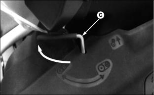
2. Push lever (C) on POWER FLOW to BELT TENSION position.
3. Check belt leading to deck sheave for tension. Close plastic deck shield. Shield tab (D) hooks under deck support tube (E).
Adjust Discharge Chute Hinge
NOTE: Discharge chute may need to be adjusted so POWER FLOW will latch to mower.

· Loosen nuts and move hinge(s) (A) back far enough to latch POWER FLOW.
Cutting Chute for POWER FLOW

1. (All Tractors) Cut off chute at point (C).
2. (420 and 430 Tractors only) Cut off end of chute at point (A).
Installing Chute
NOTE: Before installing POWER FLOW chute, MC519 Cart should be assembled and installed on tractor. See your MC519 operator manual for instructions. Bag of parts packaged with chute is NOT used.

1. Put upper end of chute (A) into upper chute (B) of cart.
NOTE: Raised area (D) on chute MUST be on top at POWER FLOW end.
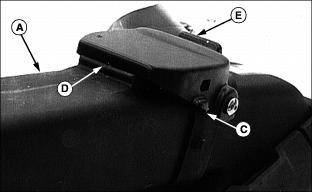
2. Put finger in notch (C) of blower discharge guard. Pull guard away from molded latch on blower chute. Push down at (E) and swing guard up.
3. Put lower end of POWER FLOW chute (A) into blower assembly with raised area (D) on chute on top. Discharge guard latches OVER raised area.