![]()
Introduction
Product Identification
Safety
Operating
Replacement Parts
Service Intervals
Service Lubrication
Service Engine
Service Transmission
Hydrostatic Transmission and Hydraulic Oil
Cleaning Hydraulic Pump Cooling Fins
Changing Hydraulic Oil and Filter
Checking and Replacing Pump Drive Belt
Checking and Adjusting Motion Control Linkages
Service Steering & Brakes
Service Mower
Service Electrical
Service Miscellaneous
Troubleshooting
Storage
Assembly
Specifications
Warranty
John Deere Quality Statement
Service Record

Service Transmission
Hydrostatic Transmission and Hydraulic Oil
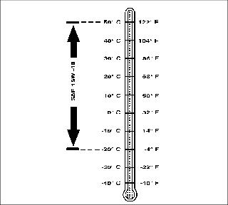
Use the following oil viscosity based on the air temperature range. Operating outside of the recommended oil air temperature range may cause premature hydrostatic transmission failure.
The following oil is preferred:
The following oil is also recommended:
The following oil is allowable:
· API Service Classification SG or higher
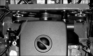
Cleaning Hydraulic Pump Cooling Fins
IMPORTANT: Avoid damage! To ensure proper cooling, keep the cooling fins clean at all times. Operating the machine with obstructed cooling fins could cause damage due to overheating. |
1. Park machine safely. (See Parking Safely in the Safety section.)
2. Lift and secure operator seat in the raised position.
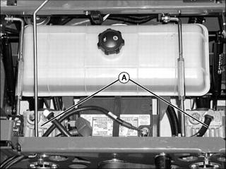
3. Clean hydraulic pump cooling fins (A) with a rag, brush, or compressed air.
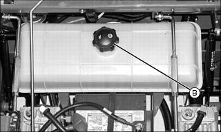
Checking Hydraulic Oil Level
IMPORTANT: Avoid damage! Check oil level in reservoir tank when oil is cold. Do not overfill oil reservoir tank. Oil will expand during operation and could overflow. |
1. Park machine safely. (Refer to Parking Safely in Safety section.)
2. Lift and secure operator seat in the raised position.
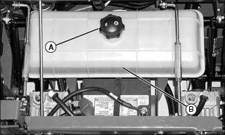
3. Thoroughly clean area around reservoir fill cap (A).
4. Visually check level of fluid. Fluid level should be even with the fill line (B) on the side of the tank.
5. To add oil, remove cap from the oil reservoir tank filler neck.
6. Install cap on filler neck.
Changing Hydraulic Oil and Filter
1. Park machine safely. (Refer to Parking Safely in the Safety section.)
2. Allow engine and hydraulic oil reservoir to cool.
3. Lift and secure operator seat in the raised position.
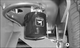
4. Turn transmission oil filter (A) counterclockwise to remove.
5. Allow transmission oil to drain into a drain pan with at least a 9.5 L (2.5 gal) capacity.
6. Apply a film of clean oil on gasket of new filter.
7. Install filter. Turn filter clockwise until gasket makes contact with the mounting surface. Tighten 1/2 to 3/4 turn after gasket contact.
8. Clean area around reservoir fill cap.
9. Remove cap (B) from the oil reservoir tank filler neck.
10. Fill oil reservoir with approximately 7.6 L (2 gal) of oil.
12. Move throttle lever to the fast position.
14. Cycle motion control levers forward and rearward several times. Check for leaks around filter.
15. Stop the engine. Check oil level. Add oil as necessary.
Checking and Replacing Pump Drive Belt
NOTE: The transmission drive belt will not require a tension adjustment. Belt is self-adjusted using a spring tensioner.
Checking Belt:
1. Stop engine and lock park brake.
2. Lift and secure operator seat in the raised position.
3. Inspect belt (A) for excessive wear, damage or stretching while in position on the transmission sheaves and drive belt tensioner pulley.
Replacing Belt
1. Remove belt from drive sheaves and idler pulley.

· To make removal and installation of the belt easier, carefully move spring loaded idler (B) to the left using a pry bar.
2. Install belt onto drive sheaves and idler pulley as shown.
Checking and Adjusting Motion Control Linkages
Checking Motion Control Linkages
NOTE: Check and adjust motion control linkages with the machine parked on a hard, level surface.
· If it is necessary to run an engine in an enclosed area, use an exhaust pipe extension to remove the fumes. |
2. Set throttle lever to the fast position.
4. If the rear drive wheels begin to creep, an adjustment is required.
Adjusting Motion Control Linkages
1. Stop engine and lock park brake.

2. Move both motion control levers (A) to the neutral lock position.
3. Lift and secure operator seat in the raised position.
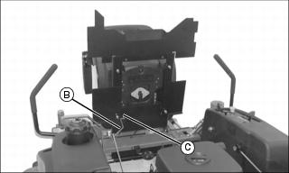
4. Remove support rod (B) from side of seat frame.
· Remove cotter pin and washer (C).
5. Tilt seat forward to rest on front frame.
6. Raise rear of machine with a safe lifting device.
· Support with wood blocks or jackstands.
· Rear drive wheels must have the ability to rotate freely.
7. Activate operator seat safety switch.
NOTE: To prevent damage to the bottom of the operator seat, cover end of wood block with a rag.
· Place a wood block approximately 25-30 cm (10-12 in.) long between the foot plate and the center of the seat.
9. Set throttle to the fast position.
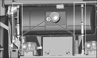
11. Locate left and right motion control linkages (D).
12. Move the right motion control lever into the neutral lock position.
· The right drive wheel must not turn. If it does turn, adjust the motion control linkage:
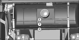
a. Loosen hex nuts (E) and hex nuts (G) on each side of the turnbuckle (F).
b. Adjust turnbuckle (F). Keep adjusting the turnbuckle until the wheel stops rotating completely.
c. Tighten hex nuts (E and G) against turnbuckle (F).
13. Move the right motion control lever completely rearward in the slot and release lever. The lever should return back to the neutral position (completely centered in the slot).
· The drive wheels must stop completely.If the drive wheel does not completely stop rotating, a damper mount adjustment is necessary:
· Adjust damper in slot as necessary, tighten nut to 20 Nüm (15 ft-lb).
14. Move the right motion control lever completely forward and rearward in the slot and then back to the neutral lock position.
· The drive wheels must stop completely. If the drive wheel does not completely stop rotating, repeat steps12 and 13.
15. Repeat procedure to adjust the left motion control linkage.
17. Move both motion control levers to the neutral lock position.
18. Remove wood block from between foot plate and the operator seat.
20. Install support rod to side of seat frame with cotter pin and washer.