Introduction
Product Identification
Safety
Operating
Replacement Parts
Service Intervals
Service Lubrication
Service Engine
Service Transmission
Service Steering & Brakes
Service Mower
Service Electrical
Service Miscellaneous
Troubleshooting
Storage
Assembly
Check Machine Safety Interlock System
Specifications
Warranty
John Deere Quality Statement
Service Record

Assembly
Bag of Parts
Prepare for Assembly
· Remove machine from the shipping crate:
· Cut plastic tie straps fastening the rear drive wheels to the shipping crate.
· Cut tie bands fastening the rear of the machine to the shipping crate pedestal.
· Cut plastic tie straps fastening the front wheels to the shipping crate.
· Cut plastic tie straps fastening the rollers on the front of the deck to the shipping crate.
· Cut plastic tie straps fastening the motion control levers to the foot plate.
· Remove protector from fuel tank neck and install fuel tank cap.
Install Rear Drive Wheels
1. Remove eight lug nuts from bag of parts.
2. Lift rear of machine with a safe lifting device.
3. Check drive wheel tire inflation pressures:
· Keep tires inflated to 69-97 kPa (10-14 psi).
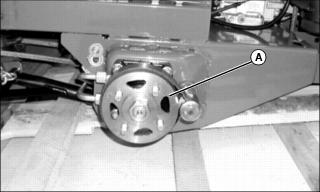
4. Attach one wheel to each hub (A) using four lug nuts, tighten until snug.
· Mount each wheel with the valve stem facing to the outside.
5. Lift front of machine with a safe lifting device
6. Remove shipping crate base from under machine.
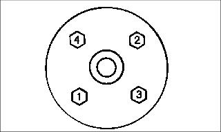
· Tighten wheel nuts in numbered sequence shown for safe wheel installation. Tighten alternately until recommended torque value is reached.
· Tighten nuts to 100 N·m (75 lb-ft).
Check Tire Pressure
2. Check tire pressure with an accurate gauge.
Install Motion Control Levers
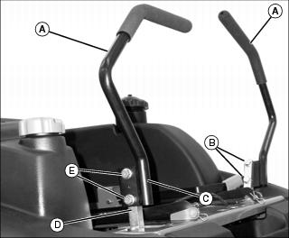
1. Install each motion control lever (A) to the outside of the control arm (D) with two M10 flange screws (E) and two M10 hex flange lock nuts (B).
· Motion control lever tabs (C) should be directed to the rear of the mower.
· Position each motion control lever so the attaching hardware is installed in the center of the slotted tab holes.
2. Check motion control lever alignment.
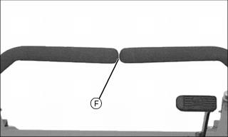
· Move both motion control levers forward.
· Check gap (F) between the levers. The recommended gap is 3-6 mm (1/8-1/4 in.).
NOTE: If the ends of the levers strike against each other while in the neutral position, move the levers outward to the neutral lock position and carefully bend them outward. Move them back to the neutral position and check for the recommended gap of 3-6 mm (1/8 - 1/4 in.).
· Check levers for equal alignment.
· If positions of the levers are unequal, loosen attaching hardware and slide both levers forward or rearward to desired position within tab slots until levers are aligned.
Connect Battery
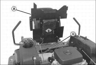
1. Raise seat frame (A) until support rod (B) locks.
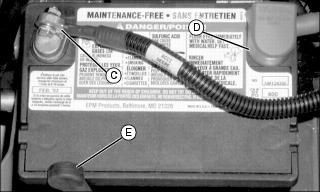
2. Connect positive (red) cable to battery.
· Install red terminal cover (D).
3. Connect negative (black) cable (C) to battery.
4. Secure rubber hold-down strap (E).
Install Seat
1. Move the motion control levers to the swing-out neutral lock position.
2. Remove protective covers from seat screws.
3. Determine proper bolt pattern for seat type:
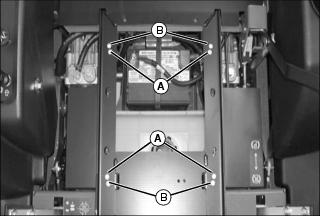
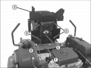
4. Raise seat frame (C) until support rod (G) locks. Secure seat to frame with M8 lock nuts (D).
5. Connect harness (E) on seat to harness (F) on machine.
Check Engine Oil Level
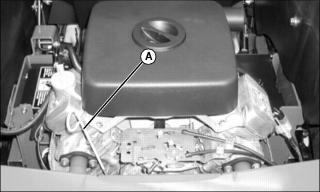
1. Remove oil dipstick (A). Wipe it clean.
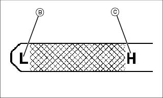
3. Remove dipstick and check oil level. Oil level must be between "low" (B) and "high" (C) marks on dipstick.
Check Mower Deck Level
The mower deck is assembled and adjusted at the factory. After machine is completely assembled check the mower "Front to Rear" and "Side to Side" deck level.
Check Machine Safety Interlock System
Perform safety system check to make sure the electronic safety interlock circuit is functioning properly.

