![]()
38-Inch for F510 and F525 Front Mowers
Introduction
Safety Signs
Preparing Vehicle
Installing
Removing
Operating
Service Machine Safely
Service
Troubleshooting
Storing Machine
Assembly
Specifications
John Deere Service Literature
John Deere Quality Statement
Copyright© Deere & Company

Assembly
Identify Parts
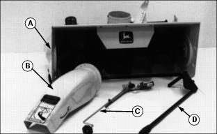
Bag of Parts
Assemble Snowthrower
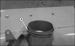
1. Apply John Deere Moly High Temperature EP Grease or an equivalent on chute base (A).
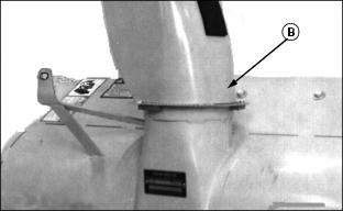
2. Put discharge chute (B) on base.
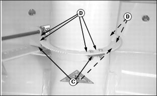
3. Fasten chute to base with three clips (C) and six M5 x 20 bolts and lock nuts (D).
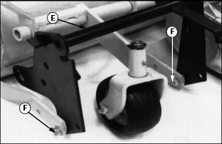
· Remove lift bracket (E) from snowthrower.
· Remove two bolts M12 x 1.75 x 30 mm and lock nuts (F) from lift bracket.
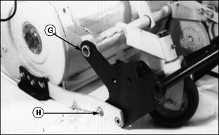
· Install lift bracket to snowthrower pivot shaft (G).
· Install two bolts M12 x 1.75 x 30 mm and two lock nuts (H) through lift arm and bracket. Put in holes closest to snowthrower. DO NOT tighten.
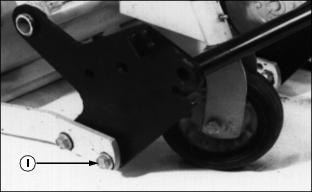
· Install two bolts M12 x 1.75 x 30 mm and lock nuts (I) in holes closest to Front Mower.
· Tighten four bolts and lock nuts.
5. Install right caster wheel:
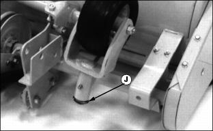
· Remove E-clip (J) from right caster wheel.
· Remove caster wheel assembly from spindle. Turn end for end. Insert caster wheel in spindle.
· Remove rubber cap from shaft on lift arm.
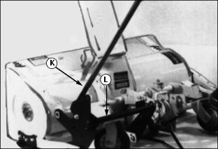
· Push lift handle (K) into shaft of lift bracket (L). Welded rivet on lift arm MUST slide into groove in lift bracket.
· Pull rearward until latch catches.
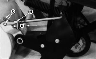
· Attach yoke (M) to threaded end of lift rod. Adjust rod to 28 mm (1-1/8 in.), length of exposed thread (N). (See Adjusting Lift Height in Operating Snowthrower section.)
· Insert one drilled pin and spring locking pin (O) through yoke and bracket.
· Push button on lift lever and push forward to release latch.
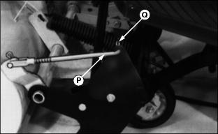
· Install lift rod (P) in lift bracket.
8. Install lift assist spring:
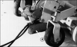
· Insert block of wood (R) under snowthrower bracket located under idler.
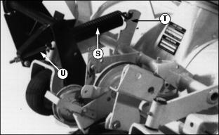
· Install spring (S) to snowthrower bracket (T).
NOTE: Loosen upstop hardware before you install eye bolt.
· Install eye bolt (U) through other end of spring.
NOTE: Threaded end of eye bolt MUST be facing Front Mower.
· Put threaded end of eye bolt through welded strap on lift bracket.
NOTE: Make sure both nuts are located to back side of welded strap on lift bracket
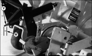
9. Put two M10 nuts (V) on threaded end of eye bolt.
10. Adjust tension on eye bolt until Dimension (W) is 35-40 mm (1.4-1.6 in.).
11. Tighten second nut until it locks.
Install Spout Control Rod
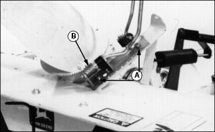
1. Install two carriage bolts M8 x 1.25 x 25 and two flanged lock nuts (A) through spout control rod bracket and snowthrower bracket.
2. Position worm gear so grooves on gear mesh with teeth on discharge spout.
3. Put John Deere Moly High Temperature EP Grease or an equivalent on worm gear (B).
4. Spout MUST rotate freely when turning crank handle.
6. If snowthrower spout starts rotating on its own while blowing snow, turn nut under black tension block up to adjust tension.
7. Adjust runners. (See Adjusting Runners in Operating section.)
Install Reflective Tape
NOTE: Reflective tape is in Front Mower operator's manual bag.
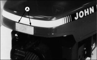
Install piece of reflective tape (A) in center of Front Mower hood.
NOTE: Adjust upstop to 2-5 mm (0.078-0.197 -in.). (See Adjusting Upstop in Operating Snowthrower section.)