![]()
Introduction
Safety Signs
Controls
Operating Machine
Replacement Parts
Service Machine Safely
Service Interval Chart
Service Engine
Service Transmission
Service-Brakes and Drive Wheels
Service Mower
Avoid Injury From Contacting Blades
Lubricating Mower Spindles (36-Inch Decks)
Lubricating Mower Spindles (48/54-Inch Decks)
Lubricating Mower Deck Idler Arm (48/54-Inch Decks)
Replacing Clutch To Mower Deck Drive Belt (36-Inch Decks)
Replacing Mower Deck Timing Belt (36-Inch Decks)
Quick Check On Mower Deck Timing (36-Inch Decks)
Adjusting Mower Deck Timing (36-Inch Decks)
Adjusting Timing Belt Tension (36-Inch Decks)
Replacing Clutch To Mower Deck Drive Belt (48/54-Inch Decks)
Level Mower Deck (Front-To-Rear)
Level Mower Deck (Side-to-Side)
Inspecting and Replacing Mower Blades
Service Electrical
Service Miscellaneous
Troubleshooting
Storing Machine
Assembly
Specifications
Warranty
John Deere Service Literature
Quality Doesn't End When You Invest In A Deere
Copyright© Deere & Company

Service Mower
Avoid Injury From Contacting Blades

Grease
Use grease based on the expected air temperature range during the service interval.
The following greases are preferred:

· John Deere Moly High Temperature EP Grease.
· John Deere High Temperature EP Grease.
Other greases may be used are:
· SAE Multipurpose EP Grease with 3 to 5 percent molybdenum disulfide.
· Greases meeting Military Specification MIL-G-10924C may be used as arctic grease.
Lubricating Mower Spindles (36-Inch Decks)
· Lubricate at least every 25 hours of operation.

Lubricate mower spindles grease fittings (A) with John Deere Moly High Temperature EP Grease or an equivalent.
Lubricating Mower Spindles (48/54-Inch Decks)

· Lubricate at least every 25 hours of operation.
Lubricate mower spindles grease fittings (A) with John Deere Moly High Temperature EP Grease or an equivalent.
Lubricating Mower Deck Idler Arm (48/54-Inch Decks)
· Lubricate at least every 25 hours of operation.


2. Loosen three belt shield screws (B).
3. Remove left belt shield (C).

4. Lubricate mower deck idler arm grease fitting (D) with John Deere Moly High Temperature EP Grease or an equivalent.
5. Install belt shield (C) and tighten screws (B).
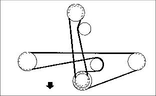
Replacing Clutch To Mower Deck Drive Belt (36-Inch Decks)
NOTE: To create more access and ease the installation of the drive belt, move the mower deck to a 2-Inch cutting height.


2. Pull spring loaded idler (B) to loosen belt tension.
3. Remove clutch to mower deck drive belt (C).
4. Install new drive belt (C) over PTO clutch sheave between the idler arm sheave and idler spring.
5. Make sure drive belt is properly routed around the spring loaded idler (B) for proper belt tension.

6. If necessary, see label on mower deck.
Replacing Mower Deck Timing Belt (36-Inch Decks)
1. Remove the clutch to mower deck drive belt (A). (See Replacing Clutch To Mower Deck Drive Belt (36-Inch Decks) in this section.)

2. Loosen timing belt tension:
· Loosen locknut (B) to the ends of the threads.
· Tension arm (D) will loosen belt tension.
3. Remove two locknuts (C) and tension arm (D).
4. Remove mower deck timing belt (E).

5. Position mower blades (F) and (G) 90° from each other.
6. Install new mower deck timing belt (E).
7. Install tension arm. Install and turn two locknuts (C) down partway to allow movement of tension arm (D). Inspect tension arm (D), tension arm must be free to slide.
· Check that blades are still timed (90° from each other).
· Rotate blades to make sure they do not contact each other.

· If necessary, see label on mower deck.
NOTE: Lock nuts (C) must be loose to allow movement of idler arm during adjustment of lock nut (B).


· Tighten lock nut (B) to compress spring (H). Tighten lock nut until the spring side of washer (I) is even with adjustment rod end (J).
NOTE: Locknuts (C) must be tightened to prevent idler movement during mower operation. If idler is free to move, blades will become out of time.
· Tighten both lock nuts (C) to approximately 55 N·m (40 lb-ft.).
9. Install the clutch to mower deck drive belt. (See Replacing Clutch To Mower Deck Drive Belt (36-Inch Decks) in this section.)
Quick Check On Mower Deck Timing (36-Inch Decks)

2. Note the position of the drain holes (A) in the spindle sheaves. These drain holes are in alignment with the mower blades.

3. A properly timed mower deck must have the mower blades (B) and (C) at 90° from each other.
4. For a quick check on mower deck timing, sheave drain holes (A) should be approximately 90° from each other.
5. If necessary, adjust the mower deck timing. (See Adjusting Mower Deck Timing in this section.)
6. If necessary, see Adjusting Timing Belt Tension (36-Inch Decks) in this section.
7. Install mower deck belt shield.
Adjusting Mower Deck Timing (36-Inch Decks)

2. Loosen timing belt tension:
· Loosen locknut (A) to the ends of the threads.
· Tension arm (C) will loosen belt tension. Inspect tension arm (C). Tension arm must be free to slide.

3. Position mower blades (D) and (E) 90° from each other. If necessary, reposition mower blades:
· Remove two lock nuts (B) and tension arm (C).
· Slip timing belt off of one sprocket.
· Install tension arm and two lock nuts. Tension arm must be free to slide.
· Check that blades are still timed (90° from each other).
· Rotate blades to make sure they do not contact each other.
NOTE: Lock nuts (B) must be loose to allow movement of idler arm during adjustment of lock nut(A).
Lock nuts (B) must be tightened to prevent idler movement during mower operation. If idler is free to move, blades will become out of time.

· Tighten lock nut (A) to compress spring (F). Tighten lock nut until the spring side of washer (G) is even with adjustment rod end (H).

5. Tighten both lock nuts (B) to approximately 55 N·m (40 lb-ft.).
6. If necessary, see label on mower deck.
Adjusting Timing Belt Tension (36-Inch Decks)


2. Check the position of the drain holes (B) in the spindle sheaves. These drain holes are in alignment with the mower blades. If drain holes are not perpendicular to each other, the mower blades will need to be repositioned, see Adjusting Mower Deck Timing (36-Inch Decks) in this section.

3. Loosen timing belt tension:
· Tension arm (D) will move due to spring force.
· Inspect tension arm. Tension arm must be free to slide under lock nuts (C).
NOTE: Lock nuts (C) must be loose to allow movement of idler arm during adjustment of lock nut (E).
Lock nuts (C) must be tightened to prevent idler movement during mower operation. If idler is free to move, blades will become out of time.

· Tighten lock nut (E) to compress spring (F). Tighten lock nut until the spring side of washer (G) is even with adjustment rod end (H).
5. Tighten both lock nuts (C) to approximately 55 N·m (40 lb-ft.)
6. If necessary, see label on mower deck.
Replacing Clutch To Mower Deck Drive Belt (48/54-Inch Decks)


2. Pull spring loaded idler (B) to loosen belt tension.
3. Remove and replace clutch to mower deck drive belt (C).
4. Make sure drive belt is properly routed around the spring loaded idler (B) for proper belt tension.
5. If necessary, see label on mower deck.
Level Mower Deck (Front-To-Rear)
Blades may have sharp edges. Wear heavy gloves or use a rag to protect hands. |
NOTE: Before checking mower deck front to rear level, check mower deck for the correct combination of cut height adjustments. See Adjusting Mower Deck Height in the Operating section.
1. Park mower on a hard level surface.
2. Check tire pressure: 100-200 kPa (15-28 psi).
3. Raise mower deck to the highest cutting position. Check for:
NOTE: Use a short ruler or leveling gauge (B). Order gauge from your John Deere Dealer.

4. Position left mower blade in the horizontal position shown.
5. Measure from left front blade tip to floor. Turn blade 180° and measure from left rear tip to floor: Distance (A).
6. Repeat Steps 4 and 5 for right blade.
7. Distance (A) at rear of blade should be 3-6 mm (1/8-1/4 in.) more than Distance (A) at front of blade.
Level mower deck (front to rear) using mower deck attaching hardware or caster wheel washers.
8. Mower deck attaching hardware:

· Loosen mower deck to power unit attaching hardware (C).
· Level deck by rotating power unit with respect to the mower deck and tighten attaching hardware.
· Tighten locknuts to 140 N·m (105 lb-ft.).
NOTE: Caster wheel washers should be used as a fine tune adjustment for front to rear leveling.
Always adjust left and right caster wheels equally, when adjusting level front to rear.
· Raise and block one side of mower deck 150 mm (6 in.).

· Remove caster wheel from mower.
· Move top washer (E) to bottom position to RAISE front of mower, OR move washer (F) from bottom to top to LOWER front of mower.
10. Check mower level. (Repeat Steps 4 and 5).
Level Mower Deck (Side-to-Side)
Blades may have sharp edges. Wear heavy gloves or use a rag to protect hands. |
NOTE: Before checking mower deck side-to-side level, check mower deck for the correct combination of cut height adjustments. See Adjusting Mower Deck Height in the Operating section.
1. Park mower on a hard level surface.
2. Check tire pressure: 100-200 kPa (15-28 psi).
3. Raise mower deck to the highest cutting position. Check for:
NOTE: Use a short ruler or leveling gauge (B). Order gauge from your John Deere dealer.
4. Position left mower blade into a sideways (horizontal) position.

5. Measure from left blade tip to floor. Distance (A).
6. Turn the right mower blade to the same sideways (horizontal) position. Measure distance (A) from tip of blade to the floor.
7. Distance (A) should be the same on each side 3 mm (1/8 in.)

8. If a side-to-side mower deck adjustment is needed, adjust caster wheel washers:
· Raise and block one side of mower 150 mm (6 in.).
· Move top washer (D) to bottom position (E) to lower wheel.
9. Check mower level. (Repeat steps 4-7).
Inspecting and Replacing Mower Blades
1. Raise and block front of mower.

· Mower blades should be sharp and free of any damage.
· Replace mower blades as required.
3. Remove and replace damaged blade(s):
· Remove blade bolt (B), washer (C) and blade (A). Discard any blade that has been damaged due to a serious impact.
· When installing a new blade, put cup-side of washer (C) against blade.
4. Remove supports and lower mower.
Sharpening Blades

1. Sharpen blades with grinder, hand file or electric blade sharpener.
2. Keep original bevel (A) when you grind.
3. Blade should have 0.40 mm (1/64 in.) cutting edge (B).
Balancing Blades

2. Put blade on nail in vise or on vertical wall stud. Turn blade to horizontal position.