![]()
Introduction
Safety Signs
Controls
Operating Machine
Rotating Blades are Dangerous - Protect Children and Prevent Accidents
Using Tracking Adjustment Knob
Using Recoil Starter Handle (HD45)
Using Park Brake Lock/Speed Limiter
Adjusting Mower Deck Front Bracket (36-Inch Decks)
Avoid Damage To Plastic And Painted Surfaces
Checking Mower Blade Stop Time
Replacement Parts
Service Machine Safely
Service Interval Chart
Service Engine
Service Transmission
Service-Brakes and Drive Wheels
Service Mower
Service Electrical
Service Miscellaneous
Troubleshooting
Storing Machine
Assembly
Specifications
Warranty
John Deere Service Literature
Quality Doesn't End When You Invest In A Deere
Copyright© Deere & Company

Operating Machine
Operate Safely

· Check brake action before you operate. Adjust or service brakes as necessary.
· Inspect machine before you operate. Be sure hardware is tight. Repair or replace damaged, badly worn, or missing parts. Be sure guards and shields are in good condition and fastened in place. Make any necessary adjustments before you operate.
· Clear work area of objects that might be thrown. Keep people and pets out of the work area. Stop machine if anyone enters the area.
· If you hit an object, stop the machine and inspect it. Make repairs before you operate. Keep machine and attachments properly maintained and in good working order.
· DO NOT leave machine unattended when it is running.
· Only operate during daylight or with good artificial light.
· Be careful of traffic when operating near or crossing roadways.
· Do not wear radio or music headphones while operating the machine. Safe operation requires your full attention.
Park Safely
· Stop machine on a level surface, not on a slope.
· Lower attachments to the ground.
· Before you leave the operator's location, wait for engine and all moving parts to STOP.
Rotating Blades are Dangerous - Protect Children and Prevent Accidents

· Never assume that children will remain where you last saw them. Children are attracted to mowing activity, stay alert to the presence of children.
· Keep children in the house when you are operating the machine.
· Turn machine off if a child enters the mowing area.
· Use extra care when you come to blind corners, shrubs, trees, or other objects that may block your vision.
· DO NOT let children or an untrained person operate the machine.
· DO NOT carry or let children ride on machine or any attachment. DO NOT tow children in a cart or trailer.
HELP PREVENT SERIOUS OR FATAL ACCIDENTS:
· Be alert at all times, drive forward carefully. People especially children can move quickly into the mowing area before you know it.
· Back carefully. Shut off PTO and look behind the machine carefully, especially for children, before you back up.
· DO NOT mow in reverse unless it is absolutely necessary.
· Shut off PTO when you are not mowing.
· DO NOT operate machine if you are under the influence of drugs or alcohol.
Operate Sulky Safely

· Use sulky ONLY on EVEN terrain for mowing mostly in a straight line.
· Be careful when you drive sulky and mower through a dip. Handlebars may hit you, ESPECIALLY when you make a turn.
· DO NOT use sulky on steep slopes.
Avoid Tipping
· DO NOT drive where machine could slip or tip.
· Stay alert for holes and other hidden hazards in the terrain.
· Slow down before you make a sharp turn or operate on a slope.
· Mow across a hill-not up and down. Be careful when you change direction on a slope.
· DO NOT stop when going up hill or down hill. If machine stops going up hill, STOP PTO and back down slowly.
· DO NOT mow wet grass. Reduced traction could cause sliding.
Operator Training Required
· Study operation section of this manual before operating the machine.
· Operate machine in an open, unobstructed area under the direction of an experienced operator.
· Learn the use of all controls.
· Operator experience is required to learn the moving, stopping, turning and other operating characteristics of the machine.
Keep Riders Off

· Only allow the operator on the sulky. Keep riders off sulky and mower.
· Riders on the machine may be struck by foreignobjects or thrown off the machine causing serious injury.
· Riders obstruct the operator's view resulting in the machine being operated in an unsafe manner.
Using Operator Presence

The operator presence system is designed to protect the operator. The operator presence bail (A) can be operated by either the left or right hand.
To operate the PTO, the operator presence bail (A) must be held down against the handlebars by the operator.
If the operator releases the operator presence bail (A) while mowing; the engine will automatically stop.
Using Steering Control Levers

The steering control levers (A & B) are used to steer the unit. When each steering control lever is sqeezed or partially squeezed, the transmission on the side the steering control lever is engaged will slow down. The left and right hand sides work independently from each other.
Left steering control lever (A) controls left drive wheel. Pull lever up to turn LEFT.
Right steering control lever (B) controls right wheel. Pull lever up to turn RIGHT.
Using Neutral Locks
The neutral locks (A) are designed to hold a transmission in neutral and give the operator the opportunity to perform a different control function.

NOTE: Left and right neutral locks work independently from each other.
1. Pull up steering control levers (B) to a neutral position. Push and engage each neutral lock (A) forward with thumbs.

· Neutral lock released into an operational position (C).

· Neutral lock pushed forward and locked in a set park brake position (D).
· Pull up steering control levers and neutral locks will automatically release.
If the neutral locks cannot be engaged, or If the neutral locks are engaged and the drive wheels begin to creep, an adjustment will be necessary. (See Adjusting Neutral Position in the Service-Transmission section.)
Using the Speed Control Lever

The functions of the Speed Selector Lever (A) are:
· Controls forward speed and reverse motion.
· Operates as a park brake position when pulled completely back to the "Z" position.
IMPORTANT: Avoid damage! Help prevent damage to the transmission. Lever engagements and releases should be gradual and performed smoothly. |
Forward:
· Move throttle lever to the "r" position.
· Hold down operator presence bail.
· Move speed control lever forward to a desirable walking speed.
· Speed range is approximately 0-8.1 km/h (0-6 mph).
· To stop forward travel, return speed control lever to the "Z" position or squeeze both steering control levers up to a neutral position.
· The transmission neutral position is adjustable. If adjustment is required, see Adjusting Neutral Position in the Service-Transmission section.
Reverse:
· Move speed control lever forward just beyond 25 mm (1 in.) from the "Z" position.
· Pull up both steering control levers to engage reverse motion.
· Reverse speed is approximately 0-1.6 km/h (0-1 mph).
· To stop reverse motion, slowly release steering control levers and return speed control lever to the "Z" position.
· The transmission neutral position and short reverse rods are adjustable. If adjustment is required, see Adjusting Neutral Position in the Service-Transmission section or Adjust Short Reverse Rods in the Service-Miscellaneous section.
The transmissions control machine forward and reverse motion. If any drivetrain slippage is suspected, check drive belt tension. (See Adjusting Transmission Drive Belt Tension in the Service-Transmission section.)
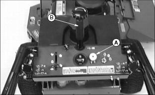
Using Tracking Adjustment Knob
NOTE: The tracking control knob should NOT be used to steer the machine.
Right and left transmission speeds will vary with travel speed and RPM variations.

The tracking adjustment knob (A) will allow the machine to maintain a straight line direction of travel.
Adjust Tracking
NOTE: To improve straight line tracking, drive wheel pressures must be equal. See Checking Tire Pressure in the Service-Miscellaneous section.
Tracking adjustment is done on-the-go at a preferred travel speed.
1. Slowly move the speed control lever forward to a desired mowing speed.
2. Turn tracking adjustment knob (A) in the direction the machine needs to move.
· Tracking knob adjustments should be done in 1/4 turn or less increments.
· If the machine moves to the left, turn the tracking adjustment knob to the right. Adjust direction of travel by pulling up the right steering control lever.
· If machine moves to the right, turn the tracking adjustment knob to the left. Adjust direction of travel by pulling up the left steering control lever.
3. Continue the adjustment process until the machine travels in a desirable straight line direction.
Using the Choke

Pull knob (A) up to CHOKE engine
Push knob (A) down to OPEN choke.
Using the Throttle Lever

Push lever (A) all the way forward to FAST position. Use this position when you mow.
Pull lever (A) to rear to SLOW position. Do not run engine at SLOW idle any longer than necessary.
Using the Hour Meter
NOTE: If machine is equipped with an electric start, the hour meter will continue to run with the key switch left on.
The hour meter (A) shows number of hours the machine has run.

The service interval chart gives necessary service intervals.
Use the hour meter and service interval chart to determine when machine will need service.
(See Service Interval Chart section.)
Using the PTO Switch
NOTE: Prior to engaging the PTO, the operator presence lever must be engaged. See Using Operator Presence Lever in this section.

Engage PTO:
· Move throttle lever (B) to the 1/2 to 3/4 FAST position.
· Move throttle lever (B) forward to the FAST (r) position for mowing.
Disengage PTO:
Using the Key Switch
Start Engine:

1. Move speed control lever (A) to the "Z" position.
2. Make sure PTO knob (B) is pushed down (disengaged).
3. Turn key switch (C) to the "e" position.
· Manual Start Model: Engine is ready to start. Pull starter handle.
· Electric Start Model: Turn key switch to the "R" position to start engine.
Stop Engine:
· Turn key switch to the "STOP" position.
Using Recoil Starter Handle (HD45)

1. Pull starter handle (A) slowly until you feel resistance within the engine.
2. Pull starter handle fast and steady. Repeat until engine starts.
3. Let starter handle return slowly. Do not let handle snap back when engine starts.
Setting the Park Brake

Picture Note: Speed control lever shown in park position.
· Pull speed control lever (A) to the "Z" position to stop forward movement.
Release Park Brake:

Picture Note: Speed control lever shown released from the park position.
· Push speed control lever (A) forward.
Using Park Brake Lock/Speed Limiter
This dual function feature will allow the speed control lever to be locked in a park position and the operator the ability to limit forward travel speed.
Park Brake Lock
· Pull speed control lever to the park position.

Picture Note: Knob shown with speed control locked in the park position.
· Slide knob (A) completely forward and tighten.
Speed Limiter
· Move speed control lever to a desirable travel speed.
· Slide knob (A) to set position and tighten.
Using Free-Wheeling Levers
IMPORTANT: Avoid damage! To prevent transmission damage, NEVER tow the mower. Push mower by hand only. |
When the mower needs to be moved without starting the engine, use the free-wheeling levers:

· Pull back and latch both free-wheeling control levers (A).
· Move speed control lever forward a minimum of 25 mm (1 in.).
· Push mower to desired location. Due to transmission gear reduction, machine will move slowly.
For normal mowing operation the free-wheeling levers (A) need to be unlatched and released forward.

Picture Note: Position (B) shows free-wheeling levers latched to the rear and engaged.

Picture Note: Position (C) shows free-wheeling levers released forward for operational mowing.
Using Fuel Shut-Off Valve

This unit is equipped with a 2-position fuel shut-off valve (A). Turn "Red" knob (B) clockwise or counterclockwise to open or close the fuel shut-off valve.
CLOSED (OFF) position (C):

· When performing any type of engine service.
OPEN (ON) position (D):
· Fuel shut-off valve must be in the full OPEN (ON) position for proper fuel delivery to the engine.
Using the Fuel Gauge

The fuel tank (A) has a built in fuel gauge.
2. Look inside fuel tank. Fuel tank has molded-in steps showing the approximate amount of fuel left in the tank.
Starting the Engine

1. Check fuel shut-off valve (A):
· Valve must be in the full OPEN (ON) position. (See Using Fuel Shut-Off Valve in this section).

2. Move speed control lever (B) to the "Z" position.
3. PTO knob (C) must be in OFF (DOWN) position.
· Cold engine: Pull knob up to the CHOKE position.
· Warm/Hot engine: If necessary, pull up knob to CHOKE position.
5. Move throttle lever (E) to set engine speed:
6. Turn key (F) to "e" position.

· Recoil Start: Pull starter handle (G) slowly until you feel resistance within the engine. Pull starter handle fast and steady. Repeat until engine starts. Let starter handle return slowly. Do not let handle snap back when engine starts.
· Electric Start: Turn key (F) to "R" position. Release key when engine starts.

· Push choke knob (D) to the OFF position.
· Move throttle lever (E) to the desired engine speed.
Stopping the Engine
IMPORTANT: Avoid damage! DO NOT stop engine when mower is on a slope of more than 10°. Oil may run through valve train into carburetor and muffler. |
Follow steps below before you park, inspect or adjust this unit.

1. Move speed control lever (A) to the "Z" position.
2. Slowly move throttle lever (B) back to the SLOW (t) position.
3. Turn key (C) to "STOP" position.

5. Move fuel shut-off valve (D) to the CLOSED (OFF) position. (See Using Fuel Shut-Off Valve in this section.)
Adjusting Mower Deck Height
36-Inch Decks
The mower deck height adjustment consists of eight different cutting heights. The eight cutting heights range from 25-114 mm (1-4.5 in.) in 13 mm (1/2 inch) increments.
48/54-Inch Decks
The mower deck height adjustment consists of nine different cutting heights. The nine cutting heights range from 25-127mm (1-5 in.) in 13 mm (1/2 inch) increments.
The cutting height indicators (B) are labeled in the mower deck support frame.
NOTE: To maintain a level mower deck, both sides, front and rear of the deck must be adjusted equally.
To change the mower deck cutting height:

Picture Note: Top photo: 36-Inch Mower Deck
· Pull out spring-loaded pins (A).

Picture Note: Bottom Photo: 48/54-Inch Mower Deck
· Lift or lower mower deck using handle (C) to the desired mower deck height indicator (B).
· Make sure spring-loaded pins are fully engaged into the mower deck support bracket holes.
Adjusting Oscillation Stops
Normal Operating Adjustment:
1. Park mower on a level surface.

3. Locate both adjustable oscillation bolts (A) mounted vertically on the front of the power deck.
NOTE: The distance between the bottom of each stop bolt head and the top of the mower deck A-frame can be reduced if less oscillation is desired.
4. Measure distance (B) between the bottom of each stop bolt head and the top of the mower deck A-frame. The recommended distance is 30 mm. This measurement would allow a maximum 6° mower deck oscillation.
5. If an adjustment is necessary:
· Loosen stop bolt jam nuts (C).
· Adjust stop bolt up or down to obtain the desired distance (B).
Operating Adjustment with Grass Catcher Option:
Restricting left side mower deck oscillation is required when optional grass catcher is used.

· Loosen left side stop bolt jam nuts (C).
· Lower left side stop bolt (A) until it makes contact with top of mower deck A-frame.
Adjusting Mower Deck Front Bracket (36-Inch Decks)

The mower deck front bracket (A) is designed to comply with Domestic (United States) and CE (European) safety standards. This bracket is essentially an extension of the front of the mower deck weldment.
In most cases this bracket should not be changed.
Bracket in lower position:
· This position is for CE (European) safety standards.
Bracket in upper position:
· This position is for Domestic (United States) safety standards.
Daily Operating Checklist
Maintain desirable operational standards and help ensure the safety of the operator by routinely checking the following on a daily basis:
· Remove grass and debris from machine.
Avoid Damage To Plastic And Painted Surfaces
· Insect repellent spray may damage plastic and painted surfaces. Do not spray insect repellent near machine.
· Be careful not to spill fuel on machine. Fuel may damage surface. Wipe up spilled fuel immediately.
Transporting Machine
· Use a heavy-duty trailer to transport your machine.
· Drive machine forward onto a trailer.
· Move speed control lever to the "Z" position.
· Fasten machine to trailer with heavy-duty straps, chains, or cables. Both front and rear straps must be directed down and outward from machine.
· Trailer must have signs and lights required by law.
Testing Safety System
NOTE: This unit is equipped with a Electronic Safety Interlock. Engine will not start unless the PTO switch is in the disengaged position and the speed control lever is in the PARK position.
Use the following checkout procedures to check for normal operation.
If there is a malfunction during one of these procedures, DO NOT operate machine. (See your John Deere dealer)
Perform these tests in a clear open area.
TEST 1
1. Push PTO switch (A) down to the DISENGAGED position.
2. Move speed control lever (B) into the "Z" position.
3. Attempt to start engine. Engine should start.
· If engine does not start, there is a problem. (See your John Deere dealer.)
Test 2

1. Pull PTO switch (A) up to the ENGAGED position.
2. Move speed control lever (B) to the "Z" position.
3. Try to start engine. Engine MUST NOT start.
· If engine starts, there is a problem with the safety interlock circuit. (See your John Deere dealer.)
TEST 3
1. Push PTO switch (A) down to the DISENGAGED position.

2. Move speed control lever (B) forward from the "Z" position.
3. Attempt to start engine. Engine MUST NOT start.
· If engine starts, there is a problem with the safety interlock circuit. (See your John Deere dealer.)
TEST 4

1. Move speed control lever (B) to the "Z" position.
2. Start engine and move throttle lever (C) to ONE-HALF speed position.
3. With operator presence lever (D) held down, pull PTO switch (A) up to the ENGAGED position. Mower deck will start up.
4. Release operator presence lever. Engine MUST stop.
· If engine does not stop, there is a problem with the safety interlock circuit. (See your John Deere dealer.)
TEST 5
1. Pull up steering control levers and engage neutral locks.

2. Move speed control lever (B) to the "Z" position.
3. Push PTO switch (A) down to the DISENGAGED position.
4. Start engine and move throttle lever (C) to ONE-HALF speed position.
5. With operator presence lever (D) held down, move the speed control lever (B) forward.
6. Release operator presence lever. Engine MUST stop.
· If engine does not stop, there is a problem with the safety interlock circuit. (See your John Deere dealer.)
TEST 6

1. Pull back and latch free-wheeling levers (E).

2. Move speed control lever (B) to the "Z" position.
3. Push and pull machine - rear wheels (drive wheels) should skid.
4. Parking brakes MUST prevent drive wheels from turning.
· If machine moves (drive wheels turn), the brakes need to be adjusted. (See Adjust Park Brake in the Service - Steering And Brakes section.)
5. Release free-wheeling levers.
Checking Mower Blade Stop Time


3. Start engine and move throttle lever (B) to the 1/2 to 3/4 FAST (r) position.
NOTE: Mower deck will engage and operate. Observe the entire mower drive system rotating.
4. With operator presence levers (D) held down, pull PTO switch (C) up to the ENGAGED position.
5. Move throttle lever (B) forward to the FAST position.
6. Check the mower blade stop time:
· Push PTO switch (C) down to the DISENGAGED position and begin timing.
· Watch mower drive belt. Note time when belt stops to get blade stop time.
· If blade stop time is more than 5 seconds, adjust PTO clutch. (See Adjusting PTO Clutch in the Service - Electrical section.)