![]()
For 4100 Compact Utility Tractor's
Introduction
Safety Signs
Installing
Removing
Operating
Replacement Parts
Service Machine Safely
Service
Troubleshooting
Assembly
Identify Front Drive & Reinforcement Kit Parts
Install Front Drive and Reinforcement Kit
Installing Discharge Chute Cables
Storing Machine
Specifications
John Deere Service Literature
John Deere Quality
Copyright© Deere & Company

ASSEMBLY
Remove Snowblower from Crate
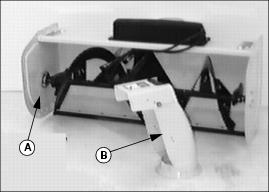
1. Remove drift blade from crate by removing bolt and washer. Discard this hardware.
2. Remove discharge chute from crate by removing two bolts and washers. Discard this hardware.
The following parts are in the bag of parts:
Identify Front Drive & Reinforcement Kit Parts
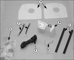
Parts listed below are found in the bag of parts:
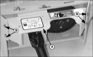
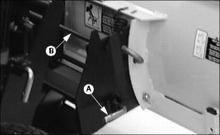
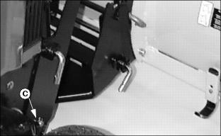
Install Front Drive and Reinforcement Kit
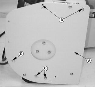
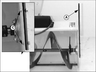
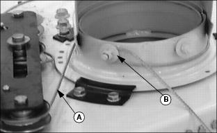
1. Remove two bolts and nuts from the skid shoe (C).
2. Bolt the reinforcement end plate (A) to the end plate of the snowblower with (3) M8x1.25x20 bolts and (3) free spinning nuts.
3. Install the 2 bolts and nuts removed in step 1 back through the end plate and skid shoes.
4. Pilot drill (3) 1/8 inch pilot holes and finish drilling (3) 5/16 mm holes (B). Deburr if necessary.
5. Install 3 more M8x1.25x20 bolts and 3 more free spinning nuts.
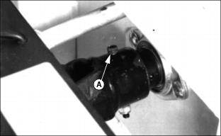
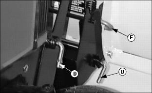
Install Driveshaft
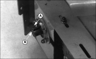
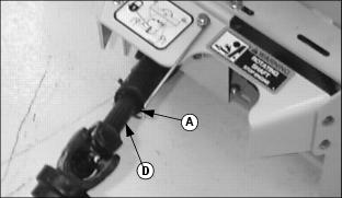
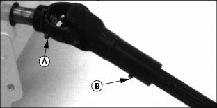
1. Install key (A) in gearbox shaft groove.
2. Apply John Deere NEVER SEEZ® lubricant or an equivalent on sprocket driveshaft (B).
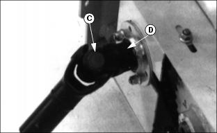
3. Align groove in driveshaft (C) with key on sprocket shaft (D) and push driveshaft on sprocket shaft.
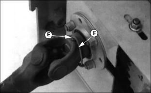
4. Align holes on sprocket shaft with holes in driveshaft and install rolled pin (E) through both shafts. Install wire (F) through rolled pin and twist both ends of wire a minimum of three turns.
Install Driveshaft shield
1. Install driveshaft shield (A) on snowblower and fasten with four M8 x 20 mm carriage bolts (B) and lock nuts. (Two on each side.)
Install PTO Support Rod
Install PTO support rod (A) onto driveshaft shield and fasten with carriage bolt, washer and lock nut (B). The washer goes between the support rod and the shield.
Use one M8x1.25x25 hex flange bolt (C)and attach the bolt to the shield with a free spinning nut for use as a PTO shield storage stop.
Put driveshaft (D) on end (A) of PTO support rod.
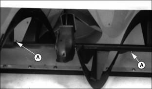
Install Drift Blade
Install drift blade (A) (one to each side of snowblower shell) with two 1-in. bolts (B) and lock nuts (C).
Install Hose Extensions
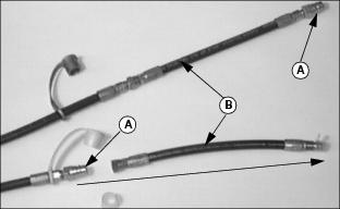
1. Remove the nipple (A) on each end of the hydraulic hose that comes with the Snowblower.
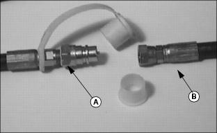
2. Install the hose extensions (B) that come in the Front drive and Reinforcement kit.
NOTE: Move protective caps to the front of the hoses.
3. Move the nipple (A) to the leading end of the hose (B) and tighten.
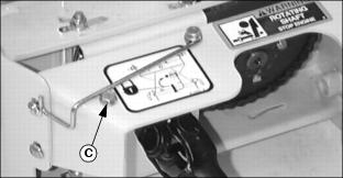
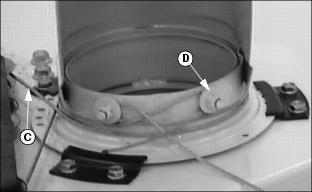
Install Discharge Chute
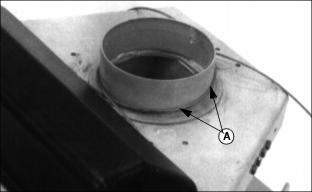
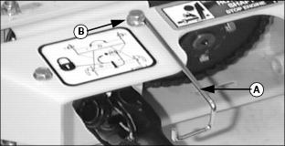
1. Put a light coat of John Deere Moly High Temperature EP Grease or an equivalent onto discharge chute base (A).
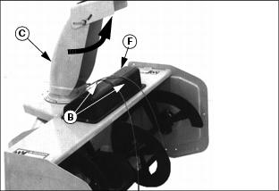
2. Lay cables (B) over snowblower shell.
3. Put discharge chute (C) on base. with chute opening facing to the LEFT. You MUST begin with chute facing to the LEFT (as viewed from tractor seat) to get proper rotation of the chute.
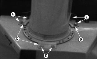
4. Install three large clips (D), and fasten with six self tapping flange hex head bolts (E).
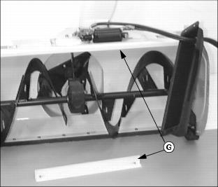
NOTE: When removing the black cable shield (F) an angle bracket (G) will fall from underneath the snowblower. This bracket needs to be installed again when the black cable shield is installed.
6. Remove black cable shield (F) by removing four bolts (H) and nuts.
7. Slide black cable shield away from pulley's.
NOTE: DO NOT install the black cable shield back on snowblower until after chute installation is complete and you have verified that chute rotation is correct.
8. Check cables to make sure they are still installed on pulleys.
Installing Discharge Chute Cables
1. Stand behind snowblower. Take left-hand cable (A) and wrap around chute clockwise.
2. Use locking pliers and pull cable tight around threaded stud, and behind lock nut, and washer (B).
4. Wrap right-hand cable (C) around chute counterclockwise.
5. Use locking pliers and pull cable tight around threaded stud, and behind lock nut, and washer(D).
NOTE: The snowblower needs to be INSTALLED on the Tractor before completing items 7-9. (See Installing section).
7. Check for EQUAL turning of chute in BOTH directions.
NOTE: If chute does not turn EQUALLY in BOTH directions after assembly, loosen nut, pull cable ends tighter, then tighten nuts.
8. Tuck excess ends of cables under cable
IMPORTANT: Avoid damage! Make sure you install the long bolts through the black cable shield and bracket. |
9. Install black cable shield and bracket with four bolts and lock nuts.
Lubricate Driveshaft
Lubricate driveshaft grease fittings with John Deere Moly High Temperature EP Grease or an equivalent as shown:
Lubricate two fittings (A) and one fitting (B).
Lubricate Auger Shaft
Lubricate grease fittings (A) with John Deere Moly High Temperature EP Grease or an equivalent.
Install Tie Strap
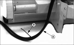
1. Fasten snowblower hydraulic hoses (A) (without a loop) and fasten with black tie strap (B).
3. Install snowblower on front hitch and check for EQUAL turning of chute in BOTH directions. See Checking Discharge Chute Rotation in the Installing Section
Assemble Broom
Fasten Driveline To Gearbox
1. Install Driveline on gearbox shaft, holes in line with shaft holes.
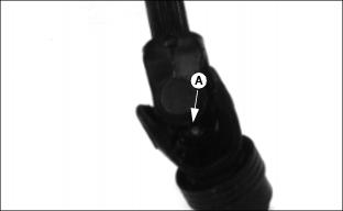
2. Install shear bolt (A) and lock nut.
NOTE: Use long shear bolt with lock nut.
Location for extra shear bolts is on the rear frame.
Assemble Blade
Fasten Front Hitch To Blade
1. Place blade on a level surface
2. Install Front Hitch to tractor. Refer to your Front Hitch Kit Instructions.
3. Release pins (A) from the LOCKED position (if locked out).
4. With hitch lowered, drive tractor slowly forward to engage rod (B) in top of hitch.
NOTE: Make sure that both pins LOCK completely into blade.
5. Raise hitch slowly until pins (A) LOCK into blade.
6. Lubricate pivot pin (C) with John Deere NEVER-SEEZ lubricant
NOTE: Photo shows blade and hitch not installed on tractor.
7. Grease L-pins (D) (two on each side), J-pin (E), and the openings they fit into with John Deere All-Purpose grease