![]()
47-Inch Front Mount for F900 Series and F1145
Introduction
Safety Signs
Preparing Vehicle
Installing
Removing
Operating
Service Safely
Service
Troubleshooting
Storing Machine
Assembly
Install Auxiliary Hydraulic Kit
Install Wheel Bracket (F900 Series Only)
Install Wheel (F900 Series Only)
Install Wheel Cylinder (F900 Series Only)
Install Hydraulic Hoses Safely
Parts for Wheel Hydraulics (F900 Series Only)
Install Long Hose (F900 Series only)
Specifications
John Deere Service Literature
John Deere Quality Statement
Copyright© Deere & Company

Assembly
Identify Parts
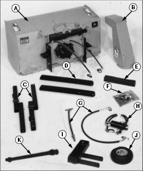
For F900 Series only (Order separately)
For all units (Ordered separately)
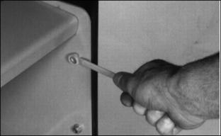
Install Auxiliary Hydraulic Kit
NOTE: Your Front Mower MUST be equipped with the Auxiliary Hydraulic Kit before installing the snowblower. See your John Deere dealer to order.
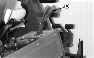
Follow instructions provided with kit to install hydraulic ports (A) and second hydraulic lever (B) to the Front Mower.
Install Lift Arms
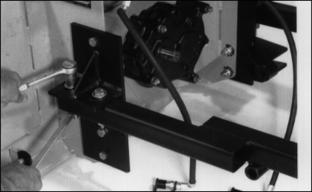
Fasten lift arms to brackets with:
· Four 1/2 x 3-in. hex-head bolts.
NOTE: At this time DO NOT tighten nuts and bolts all the way. Keep loose for ease of alignment.
Install Wheel Bracket (F900 Series Only)
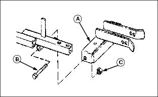
Fasten wheel bracket (A) to lift arms with two 3/4 x 3-1/2 in. cap screws (B). Wheel bracket holes are threaded. Turn in cap screws until bracket begins to tighten against lift arms. Bracket must move freely.
Install and tighten 3/4-in. jam nuts (C).
Install Wheel (F900 Series Only)
IMPORTANT: Avoid damage! Lubricate snowblower wheel bearings. DO NOT over lubricate or you may damage seal. |
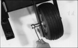
1. Install long bearing inside wheel.
NOTE: When Front Mower is equipped with oversized drive tires, install wheel in bottom holes.
2. Install wheel between arms so wheel is in line with top holes.
3. Install M12 x 1.75 x 170 mm hex head bolt with flange.
4. Install M12 self-locking nut.
5. CHECK: Tire pressure should be 320 kPa (46 psi).
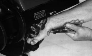
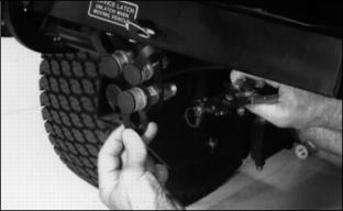
Install Wheel Cylinder (F900 Series Only)
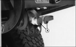
1. Install cylinder in brackets so holes are in line.
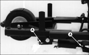
2. Install two drilled pins (A).
3. Install cotter pin in each drilled pin.
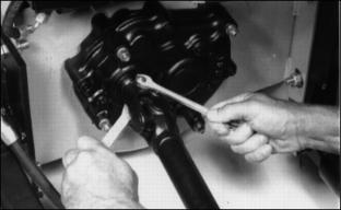
Install Driveline
1. Install key in keyway of driveshaft.
2. Install end of driveline on driveshaft so holes in both are in line.
3. Install 5/16 x 2 in. hex-head bolt and lock nut.
Install Chute
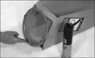
1. Apply John Deere Moly High Temperature EP Grease or equivalent on the bottom and inside flange of discharge chute.
2. Put discharge chute over auger opening.
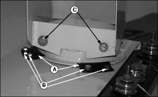
3. Install four clips (A) (two shown) with eight 5/16 x 3/4 in. cap screws, 5/16 in. lock washers, and 5/16 in. hex nuts (B)(four shown).
5. Turn chute so spout faces left.
6. Turn two 5/16 x 3/4-in. cap screws (C) with wrought washers into chute threaded holes two or three turns.
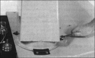
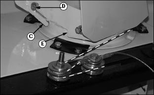
Route Chute Cables
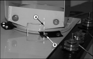
1. Move chute so tab (A) on chute is in line with edge of cap screw (B). Chute opening will be to the left.
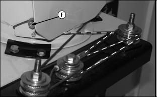
Use locking pliers to pull cable tight.
· Around bottom center pulley.
5. Use locking pliers to pull cable tight.
Install Cable Shield
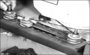
1. Install 7/16-in. washer on each cable shield bolt.
3. Install a 7/16-in. washer and elastic stop nut on each shield bolt.
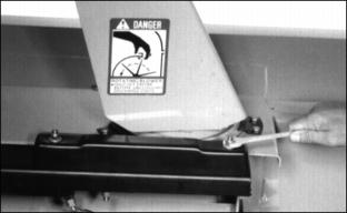
Install Drift Blade
Fasten drift blades to auger housing with four 1/4 x 1-in. carriage bolts and four 1/4-in. lock nuts.
Install Hydraulic Hoses Safely
Parts for Wheel Hydraulics (F900 Series Only)
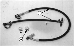
Install Short Hose
IMPORTANT: Avoid damage! Be careful short hose does not rub or interfere with other parts, especially on Front Mower with foot controls. |
1. Fasten end of hose to bracket with snap ring.
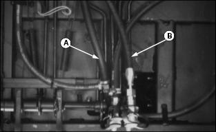
2. Hoses (A) and (B) are return lines to lift cylinders. You may connect short hose to either of these lines.
3. Put oil pan under return line you plan to use.
5. Install a hose clamp on each part of return line.
6. Connect short hose tee to return lines.
8. Use plastic straps (three in bag of parts) to tie short hose to prevent rubbing or interference with other parts.
Install Long Hose (F900 Series only)
1. Disconnect hose from fittings.
2. Fasten fittings to bracket with snap ring.
NOTE: Use plastic straps (three in bag of parts) to tie short hose to prevent rubbing or interfering.
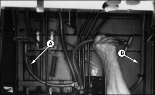
4. Route long hose (B) alongside lift cylinder hose (A) over top of right side of front axle.
NOTE: Hose (D) is from right lift cylinder.
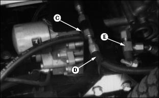
5. Put oil pan under fitting (C).
6. Disconnect LEFT lift cylinder hose from fitting (C).
7. Cut 64 mm (2 1/2 in.) from hose end you disconnected from fitting (C). (See Shorten Hydraulic Hose in this section).
8. Connect hose to left lift cylinder.
9. Connect tee of long hose (E) to hose from left cylinder and to fitting (C).
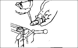
Shorten Hydraulic Hose
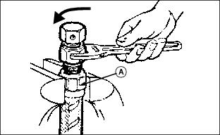
2. Turn nipple counterclockwise to remove it.
3. Move hose to vise. Turn socket clockwise to remove it from hose.
4. Remove from vise and cut hose to desired length with fine-tooth hack saw or cut-off wheel. Clean hose bore.
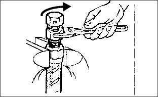
5. Put shortened hose in vise.
6. Install socket in hose end. Turn socket counterclockwise as far as it will go then back off socket 1/4-1/2 turn.
8. Lubricate nipple threads and inside of socket with heavy weight oil.
9. Turn nipple clockwise into socket.
11. Turn nipple clockwise to tighten it. Leave a maximum of 0.8 mm (1/32 in.) between nut and socket.