![]()
47-Inch Front Mount for F900 Series and F1145
Introduction
Safety Signs
Preparing Vehicle
Installing
Disengage Transmission (F900 Series)
Moving F1145 Front Mower with Engine Off
Line Up Front Mower with Snowblower
Connect Wheel Cylinder Hoses (F900 Series)
Removing
Operating
Service Safely
Service
Troubleshooting
Storing Machine
Assembly
Specifications
John Deere Service Literature
John Deere Quality Statement
Copyright© Deere & Company

Installing
Park Vehicle Safely
· Stop vehicle on a level surface, not on a slope.
· Before you leave the operator's seat, wait for engine and all moving parts to STOP.
Avoid High Pressure Fluids
· Hydraulic hoses can fail due to physical damage, kinks, age, and exposure. Check hoses regularly. Replace damaged hoses.
· Escaping fluid under pressure can penetrate the skin causing serious injury. Avoid the hazard by relieving pressure before disconnecting hydraulic or other lines. Tighten all connections before applying pressure.
· Search for leaks with a piece of cardboard. Protect hands and body from high pressure fluids.
· If an accident occurs, see a doctor immediately. Any fluid injected into the skin must be surgically removed within a few hours or gangrene may result. Doctors unfamiliar with this type of injury should reference a knowledgeable medical source. Such information is available from Deere & Company Medical Department in Moline, Illinois, U.S.A.
Put Lever in Float Position
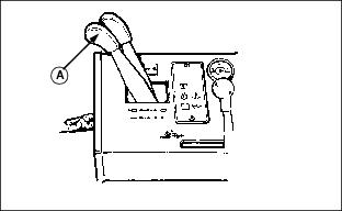
Push hydraulic lever (A) all the way forward to float position. This will let you move Front Mower lift arms by hand when engine is stopped.
Disengage Transmission (F900 Series)
1. Lift seat to service position.
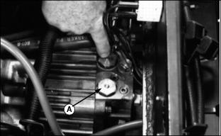
2. Push down two buttons (A) to disengage transmission. Buttons will come back up when you start engine.
Moving F1145 Front Mower with Engine Off
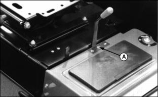
1. Shift HI-LO lever to neutral (A).
3. DO NOT move Front Mower faster than 9.6-12.9 kmh (6-8 mph). Have someone sit on seat to operate steering and brakes.
Line Up Front Mower with Snowblower
1. Park Front Mower behind snowblower. STOP engine.
2. Line up lift arms and move Front Mower lift arms up or down until snowblower lift arms will fit inside.
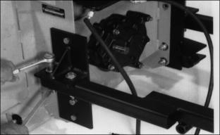
3. Tighten bolts on snowblower lift arms.
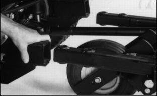
4. Push Front Mower until holes in lift arms are in line.
5. Put end of driveline up on front axle.
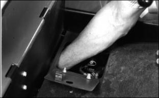
Install Lift Arm Pins
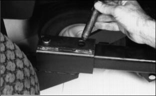
1. Install two pins in lift arms on each side.
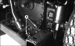
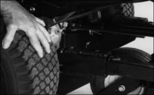
2. On F1145: Loosen jam nuts on the two left lift arm corner bolts (A).
3. Grasp outer end of this lift arm, raising it slightly to remove the play in its socket.
NOTE: DO NOT overtighten bolts.
4. Tighten bolts (A) on left lift arm to 40 Nm (30 ft-lb).
Connect Driveline
Stop the engine and be sure the PTO driveline in stopped before getting near it. |
1. Open access door. (F900 series only.)
2. Reach through access door. Pull back coupler sleeve on driveline.

3. On the F1145: Reach from the front, to connect coupler.
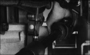
4. Align splines in coupler with driveshaft. Slide driveline onto driveshaft until coupler sleeve locks.
5. Slide driveline back and forth to make sure driveline is properly locked.
6. Close access door. (F900 series only)
Relieve Hydraulic Pressure
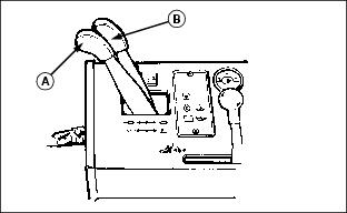
With engine off, move both hydraulic control levers (A) and (B) back and forth several times to relieve hydraulic pressure.
Connect Wheel Cylinder Hoses (F900 Series)
1. Pull dust plugs and covers from hose ends and outlets.
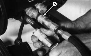
2. Push in coupler sleeve (A).
3. Install hose in coupler. Release sleeve.
5. Install hose on outlet. Release sleeve.
6. Pull on hoses to be sure couplers are LOCKED.
Connect Chute Cylinder Hoses
1. Remove dust plugs and covers from outlets and chute cylinder hose ends.
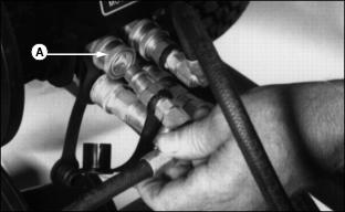
2. Push in on coupler sleeve (A). Fasten hoses to proper coupler:
· Right cylinder hose to RIGHT hydraulic outlet.
· Left cylinder hose to LEFT hydraulic outlet.
3. Pull on hoses to be sure couplers are LOCKED.
4. Install dust plugs in covers.
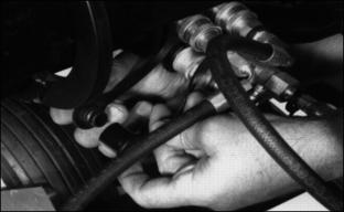
6. Operate hydraulic control levers to make sure hydraulic functions are correct.