![]()
47-Inch Front Mount for F900 Series and F1145
Introduction
Safety Signs
Preparing Vehicle
Install Auxiliary Hydraulic Kit
Install Lift Cylinder Orifices (F900 Series)
Installing
Removing
Operating
Service Safely
Service
Troubleshooting
Storing Machine
Assembly
Specifications
John Deere Service Literature
John Deere Quality Statement
Copyright© Deere & Company

Preparing Vehicle
Install Auxiliary Hydraulic Kit
NOTE: Your Front Mower MUST be equipped with the Auxiliary Hydraulic Kit before installing the snowblower. See your John Deere dealer to order.
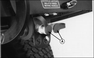
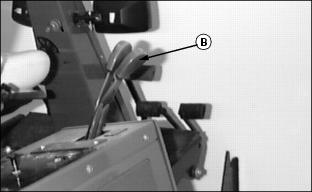
Follow instructions provided with kit BM17714 to install hydraulic ports (A) and second hydraulic lever (B) to the Front Mower.
Install Weights and Chains
·Ballasting is required for safe operation of your snowblower ·When the snowblower is removed, you MUST also remove any weights that were added to the Front Mower. |
If Front Mower is equipped with plastic rear bumper, install rear weight kit, BM17983, with six 16.78 kg (37 lb.) weights, BM17967. Follow instructions provided with kit.
If Front Mower is equipped with cast iron rear bumper, install rear weight kit, BM17983, with four 16.78 kg (37 lb.) weights, BM17967. Follow instructions provided with kit.
For F1145 six weights are required only.
Tire chains and drive wheel weights may also be used, if needed. (See your John Deere dealer.)
Install liquid weight in front tires, if needed. (See your Front Mower operator's manual.)
Install Lift Cylinder Orifices (F900 Series)
NOTE: If Front Mower is equipped with weight transfer valve, orifices are not required.
Orifices are standard on F1145's.
1. Stop engine and push hydraulic lift control lever forward to float position.
2. Pull both lift cylinder arms all the way down.
3. Clean area around lift cylinder hydraulic fitting.
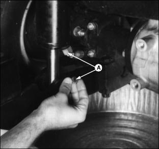
4. Disconnect hose from lift cylinder. Put orifice (A) on sealing surface of fitting. Connect and tighten fitting.
5. Follow Steps 3 and 4 for other cylinder.
6. Start engine. Operate lift cylinders to check for leaks. Tighten fittings as necessary.