![]()
Introduction
Product Identification
Safety
Preparing Vehicle
Installing
Removing
Operating
Replacement Parts
Service
Adjust Bagger Frame Tightness (LX Series Lawn Tractors with 2-Wheel Steer)
Troubleshooting
Storage
Specifications
John Deere Quality Statement
Copyright© Deere & Company

Service
Adjusting the Hopper Latch
The hopper latch is designed to maintain a tight seal between the hopper cover and body case. If the latch is difficult to operate, it can be adjusted:
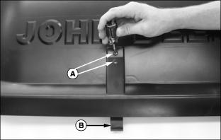
1. Loosen attaching screws (A).
2. Pull latch (B) downward to lengthen the latching distance.
3. Tighten the attaching screws.
Replacing the Grass Bags
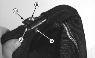
2. Mark each bag frame (A) as right or left side accordingly.
3. Remove M6 x 30 pan head screw (B), M6 locknut (C), and clip (D) from frame tube. Retain all parts.
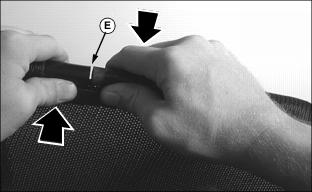
4. Slide bag around frame until seam (E) appears at one of the bag openings.
IMPORTANT: Avoid damage! Avoid distorting the frame. Do not bend apart frame ends beyond 12 mm (1/2 in.). |
5. Pull apart the frame tubes. Gently bend the tubes in opposite directions to provide 12 mm (1/2 in.) clearance between them.
NOTE: If frame position is incorrect when installing new bag, the bag will be upside down.

6. Work the bag material around the frame tube until the bag is removed.
7. Find the hole in the frame where the clip was previously installed. Then hold the frame as if it was going to be installed in the hopper. With the bag properly positioned, work the new bag onto the frame.
8. Once installed, make final adjustments to the bag until the machine safety label is positioned at the latch side of the hopper.
Adjust Bagger Frame Tightness (LX Series Lawn Tractors with 2-Wheel Steer)
NOTE: Hardware (B) on both sides of mounting frame are used to adjust the height and angle of the receiver frame.

Bagger pin (A) should be able to be removed and installed easily. When bagger pin is installed, H-frame should be held in solid.
If necessary, loosen adjusting hardware (B), adjust height and angle of receiver frame and tighten adjusting hardware.