![]()
Introduction
Product Identification
Safety
Preparing Vehicle
Installing
Install Cut-N-Throw Bagger Chute (7-Bushel Rear Bagger System Only)
Install Power Flow Chute (7-Bushel Power Flow System Only)
Removing
Operating
Replacement Parts
Service
Troubleshooting
Storage
Specifications
John Deere Quality Statement
Copyright© Deere & Company

Installing
Park Machine Safely
1. Stop machine on a level surface, not on a slope.
2. Disengage Power Take-Off (PTO).
3. Lower attachments to the ground.
7. Wait for engine and all moving parts to stop before you leave the operator's seat.
8. Close fuel shut-off valve, if your machine is equipped.
Install Ballast
Install front ballast. (See Install Proper Ballast in PREPARING VEHICLE section.)
Install Hopper Assembly
GX, SX, RX, and SRX Series Riding Mowers
1. Slide hopper H-frame (A) into mounting bracket (B).
2. Align holes in mounting bracket with top holes in H-frame. Insert pin (C) through holes and secure with spring locking pin (D).
STX Series Lawn Tractors
NOTE: For easier installation, always secure receiver frame to tractor before installing H-frame.

1. Hang receiver frame (A) onto stud (B) at both sides of rear frame.
2. Install clevis pin (C) through hole in hitch plate. Secure with spring locking pin (D).
3. From inside of rear frame, install clevis pin (E). Secure with spring locking pin (F). Repeat at opposite side of tractor.
4. Place H-frame (G) through receiver and secure with pins (H) at both sides.
LT Series Lawn Tractors
NOTE: For easier installation, always secure receiver frame to tractor before installing H-frame.
1. Hang receiver frame (A) onto stud (B) at both sides of rear frame.
2. From inside of rear frame, install clevis pin (C). Secure with spring locking pin (D). Repeat at opposite side of tractor.
3. Place H-frame through receiver frame and secure with pins (E) and (F) at both sides.
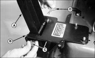
Spin-Steer Lawn Tractors

Picture Note: Bagger pin can be installed from either side.
1. Slide hopper support frame (A) between stop bracket and mounting bracket (B).
2. Align holes in mounting bracket with holes in support frame. Install bagger pin (C) through holes and secure with spring locking pin (D).

3. Check that support frame fits tightly between stop bracket and mounting bracket, and that bagger pin can be removed easily. Adjust bolts (E) if necessary.
LX Series Lawn Tractors With 2-Wheel Steer
NOTE: For easier installation, always secure receiver frame to tractor before installing H-frame.
1. Pin receiver frame to rear tractor frame with rods (A). Secure with washers (B) and spring locking pins (C).
2. Place H-frame through receiver and secure with bagger pin (D) and spring locking pin (E).
LX Series Lawn Tractors With All-Wheel Steer
NOTE: For easier installation, always secure receiver frame to tractor before installing H-frame.
1. Attach receiver frame to the frame adapter bracket:
· Hook receiver frame slotted adapter plates onto the frame adapter bracket.
· Align holes in receiver frame with holes in frame adapter bracket. Insert retaining rod (A) through holes.
· Install flat washer (B) onto rod end and secure with spring locking pin (C).
2. Place H-frame through receiver and secure with bagger pin (D) and spring locking pin (E).
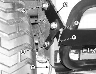
GT and 300 Series Lawn and Garden Tractors
NOTE: For easier installation, always secure receiver frame to tractor before installing H-frame.

1. Position receiver frame onto stud (A) at both sides of tractor.
2. From inside of rear frame, install clevis pins (B). Secure with washers (C) and spring locking pins (D).
3. Install clevis pin (E) through hole in hitch plate. Secure with spring locking pin (F).
4. Place H-frame through receiver opening. Install bagger pin (G) and secure with spring locking pin (H).
400 Series Lawn and Garden Tractors

1. Pull outward and rotate to lockout J-pin (A) at both sides of H-frame (B).
NOTE: On early model 400 Series tractors, H-frame welded pin is inserted into center hole (C).
2. Insert H-frame welded pin (D) into outer hole in hitch plate.
IMPORTANT: Avoid damage! On units with 3-point hitch, when attaching bagger bracket, both hitch pins should be captured between U-bracket weldments on bagger frame. |

3. On tractors with 3-point hitch, both hitch pins (E) should be captured between U-bracket weldments on bagger frame

4. Align hole in outer bracket (F) with hole in mounting strap (G). Lock J-pin into holes. Repeat for other J-pin.
Install Cut-N-Throw Bagger Chute (7-Bushel Rear Bagger System Only)
30 and 38-Inch Mower Decks
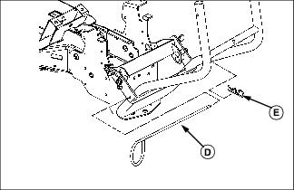
1. Insert round end of bagger chute (A) into upper chute (B) at hopper assembly.

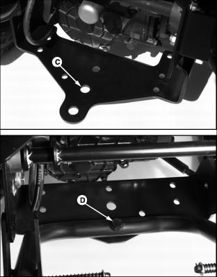
2. Lift up discharge chute at mower deck and fit bagger chute opening over mower deck discharge chute. Make sure discharge chute is properly hooked at back side of discharge opening (C).
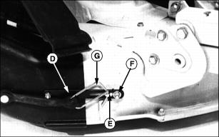
3. Place retaining strap (D) over tab (E).
4. Slide adjusting hardware (F) against tab (E). Adjust hardware, if necessary, to secure the attachment.
5. Secure rubber strap hook (G) through hole in tab (E).
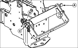
42C Mower Decks

1. Insert round end of bagger chute (A) into upper chute (B) at hopper assembly.
2. Lift up discharge shield (C) and deflector (D).
3. Fit chute (E) over discharge opening. Make sure lower edge of chute is seated completely in lip (F).
4. Place slot in retaining bracket (G) over tab on mower deck. Secure front hook (H) through hole in tab.
5. Secure rear hook (I) through hole in mower deck lip.
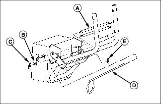
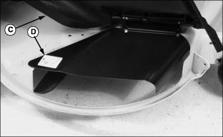
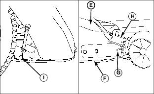
42 All Purpose Mower Decks (For Spin-Steer Only)
NOTE: For easier installation, lower the mower deck cutting height to 51 mm (2 in.) or less.

1. Insert round end of bagger chute (A) into upper chute (B) at hopper assembly.

2. Lift up discharge shield (C) and deflector (D).
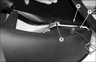
3. Put anchoring rod (E) through opening under discharge deflector as shown and fit chute over discharge opening. Make sure tab (F) is positioned inside hinge bracket slot (G).
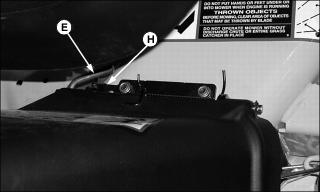
4. Hook anchoring rod (E) behind hinge bracket (H) on top of discharge shield.

5. Check that lower edge of chute is seated completely in lip (I). It may be necessary to clean debris from lip.
6. Secure two chute hooks (J) through hooks on mower deck.
Install Power Flow Chute (7-Bushel Power Flow System Only)

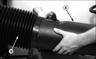
1. Insert round end of power flow chute (A) into upper chute (B) at hopper assembly.
2. If necessary, hold open exhaust door on blower assembly. Slide square end of power flow chute over blower outlet.
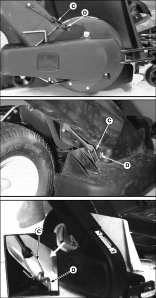
Picture Note: Top photo - 38QT and 48QT Power Flow, middle photo - 38 and 46 - Inch Power Flow, bottom photo - 48 and 54 - Inch Power Flow.