![]()
Introduction
Product Identification
Safety
Preparing Vehicle
Installing
Removing
Remove Rear Bagger Chute (7-Bushel Rear Bagger System Only)
Remove Power Flow Chute (7-Bushel Power Flow System Only)
Operating
Replacement Parts
Service
Troubleshooting
Storage
Specifications
John Deere Quality Statement
Copyright© Deere & Company

Removing
Park Machine Safely
1. Stop machine on a level surface, not on a slope.
2. Disengage Power Take-Off (PTO).
3. Lower attachments to the ground.
7. Wait for engine and all moving parts to stop before you leave the operator's seat.
8. Close fuel shut-off valve, if your machine is equipped.
Remove Ballast
Remove front ballast. This will ensure proper operation of the machine when material collection system is not installed.
On Spin-Steer Lawn Tractors Only
2. Open hood and remove front suitcase weight.
Remove Rear Bagger Chute (7-Bushel Rear Bagger System Only)
30 and 38-Inch Mower Decks
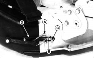
1. Release rubber strap hook (A) from tab (B).
2. Loosen adjusting hardware (C), if desired.
3. Remove retaining strap (D) from tab (B). Lift chute from mower deck.

4. Remove bagger chute from upper chute (E) at hopper assembly.
42C Mower Decks

1. Release rubber strap hooks (A) and (B). Lift chute from mower deck.

2. Remove bagger chute from upper chute (C) at hopper assembly.
42 All Purpose Mower Decks (For Spin-Steer Only)
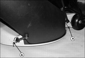
1. Release rubber strap hooks (A). Lift chute from mower deck.

2. Remove bagger chute from upper chute (B) at hopper assembly.
Remove Power Flow Chute (7-Bushel Power Flow System Only)

Picture Note: Top photo - 38QT and 48QT Power Flow, middle photo - 38 and 46 - Inch Power Flow, bottom photo - 48 and 54 - Inch Power Flow.
2. Lift chute off blower outlet.

3. Remove round end of power flow chute from upper chute (B) at hopper assembly.
Remove Hopper Assembly
IMPORTANT: Avoid damage! To avoid scratches to the hopper assembly, set it on a non-abrasive surface after removal. |
NOTE: After removing hopper assembly, always install the attaching hardware to the hopper frame to prevent loss of parts.
GX, SX, RX, and SRX Series Riding Mowers
1. Remove spring locking pin (A) and pin (B).
2. Lift hopper assembly upward to disengage H-frame (C) from mounting bracket (D).
STX Series Lawn Tractors
NOTE: For easier removal, always remove H-frame first.
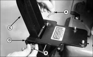
1. Remove pins (A) at both sides of receiver frame. Lift H-frame from receiver.
2. Remove spring locking pin (B) and clevis pin (C) at both sides of rear frame.
3. Remove spring locking pin (D) and clevis pin (E) from hitch plate.
LT Series Lawn Tractors
NOTE: For easier removal, always remove H-frame first.
1. Remove pins (A) and (B) at both sides of receiver. Lift H-frame from receiver.
2. Remove spring locking pin (C) and clevis pin (D) at both sides of rear frame.
Spin-Steer Lawn Tractors
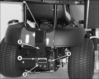
1. Remove spring locking pin (A) and bagger pin (B).
2. Lift hopper assembly upward to remove support frame (C) from mounting bracket (D).
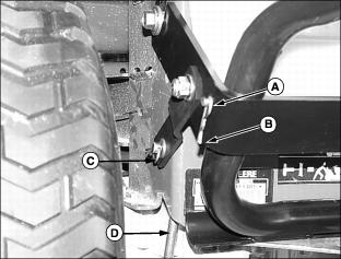
LX Series Lawn Tractors With 2-Wheel Steer
NOTE: For easier removal, always remove H-frame first.
1. Remove spring pin (E) and bagger pin (D) securing H-frame to receiver frame. Lift H-frame from receiver.
2. Remove spring pins (C), flat washers (B), rods (A) and receiver frame.
LX Series Lawn Tractors With All-Wheel Steer
NOTE: For easier removal, always remove H-frame first.
1. Remove spring pin (A) and bagger pin (B) securing H-frame to receiver frame. Lift H-frame from receiver.
2. Remove spring pin (D), flat washer (C), rod (A) and receiver frame.
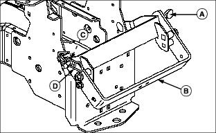
GT and 300 Series Lawn and Garden Tractors
NOTE: For easier installation, always secure receiver frame to tractor before installing H-frame.
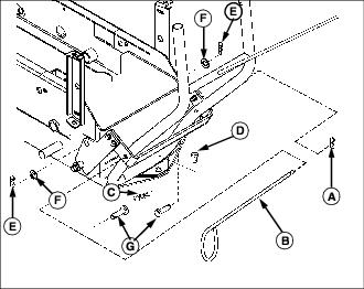
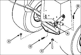
1. Remove spring locking pin (A) and bagger pin (B) securing H-frame to receiver frame. Lift H-frame from receiver.
2. Remove spring locking pin (C) and clevis pin (D) from hitch plate.
3. Remove spring locking pins (E) and washers (F).
4. From inside of rear frame, remove clevis pins (G). Lift receiver from rear frame.
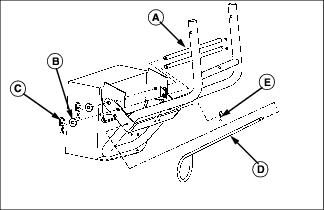
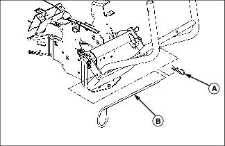
400 Series Lawn and Garden Tractors
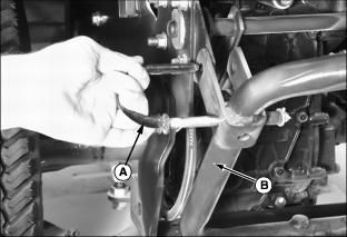
2. Pull outward and rotate to lockout J-pin (A) at both sides of H-frame (B).
3. Lift hopper assembly from rear frame.
NOTE: When the bagger is removed, it is suggested that both tie straps be removed from the 3-point hitch pins and installed somewhere on the bagger frame so they can be used next time bagger is installed.
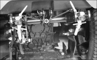
4. On tractors with 3-point hitch, remove both tie straps (C). Put both tie straps somewhere on the bagger H-frame so they can be used next time bagger is installed.
Change Mower Blades
If special blades were installed for bagging, remove them. Install correct blades for your next mowing application. If necessary, see Install Proper Mower Blades in the PREPARING THE VEHICLE section.