![]()
Introduction
Safety Signs
Controls
Operating
Operating Cutting Units
Replacement Parts
Service Machine Safely
Service Interval Chart
Service Lubrication
Service Engine
Changing Engine Oil And Filter
Cleaning Plenum Air Intake Screens
Checking Air Restriction Indicator
Clean Rubber Dust Unloading Valve
Cleaning Fuel Filter Sediment Bowl
Service Transmission
Service Cutting Units
Service Electrical
Service Miscellaneous
Troubleshooting
Storing Machine
Assembly
Specifications
Warranty
John Deere Service Literature
John Deere Quality Statement
Copyright© Deere & Company

Service Engine
Avoid Fumes
· If it is necessary to run an engine in an enclosed area, use an exhaust pipe extension to remove the fumes. |
Engine Oil
Use oil viscosity based on the expected air temperature range during the period between oil changes.
The following oil is preferred:
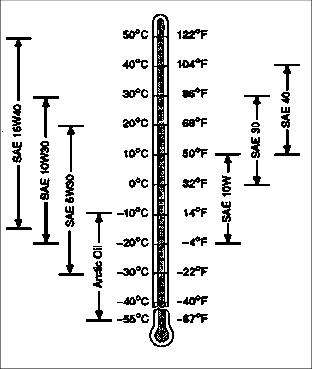
The following oil is also recommended:
· John Deere TORQGARD SUPREME®
Other oils may be used if they meet one of the following:
· API Service Classification CE
· API Service Classification CD
Viscosity grade SAE 15W-40 is preferred.
If John Deere PLUS-50 engine oil and a John Deere oil filter are used, the oil and filter service interval may be extended by 50 hours.
If diesel fuel exceeding 0.5% sulfur content is used, reduce the service interval for engine oil and filter by 50%.
Checking Engine Oil Level
NOTE: Check oil twice a day if engine is run over 4 hours a day.
3. Check engine oil when oil is cold.
4. Lift the hood. (See Raising Hood in Service-Miscellaneous section)
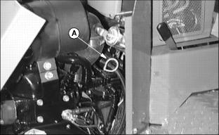
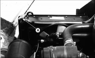
6. Clean around dipstick. Remove dipstick (A).
8. Remove dipstick. Check oil level on dipstick.
9. Oil must be between ADD and FULL marks.
10. If oil level is low, add oil to bring oil level no higher than FULL mark on dipstick. (See Engine Oil in this section for correct oil.)
11. Install the dipstick. Lower the hood.
12. If oil level is above full mark, drain to the proper level. Determine cause of over-full condition and correct.
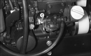
Changing Engine Oil And Filter
NOTE: Access to oil filter and drain plug is improved by disconnecting the center cutting unit from the lift arm and sliding it out of the way.
1. Run engine to warm the oil.
2. Park mower on level surface and lower cutting units.
3. Stop the engine. Lock the park brake and remove the key.
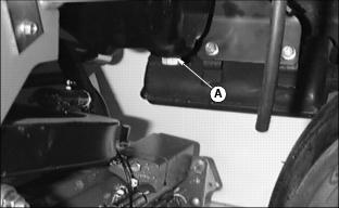
4. Remove drain plug (A) to drain oil.
5. Remove oil filter (B) (not shown). Turn filter counterclockwise to remove.
6. Apply a film of clean engine oil on seal of new filter.
7. Install filter. Turn filter until seal contacts mounting surface. Tighten 1/2-3/4 turn after gasket contact.
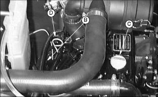
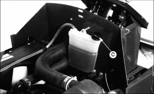
9. Remove filler cap (C). Add approximately 2.4 L (2.5 qt) of oil. (See Engine Oil in this section for correct oil.)
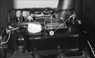
10. Remove the dipstick (D) to check oil level.
11. Install and tighten the filler cap.
12. Run engine at slow speed 2 minutes. Check for leaks around filter.
13. Stop the engine and wait a couple of minutes. Check oil level. Add oil only to FULL mark on dipstick.
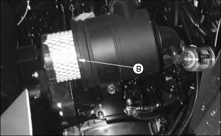
Cleaning Plenum Air Intake Screens
IMPORTANT: Avoid damage! Plenum intake screen must be clear of dirt and debris to prevent engine from overheating. |
1. Stop the engine. Lock the park brake and remove the key.
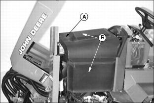
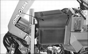
3. Remove plenum (A) by lifting up and away from engine.
4. Clean plenum air intake screens (B) (top and sides) with brush or compressed air.
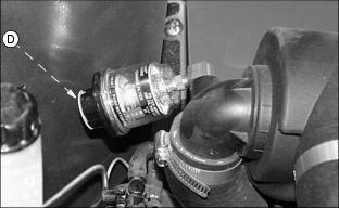
Checking Air Restriction Indicator
1. Stop the engine. Lock the park brake and remove the key.
NOTE: Indicator will not signal correctly if indicator case is cracked or broken.
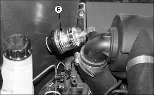
4. Check air restriction indicator: When yellow plunger (B) inside indicator shows in clear window, air cleaner requires immediate service. (See Replacing Air Cleaner Element in this section.)
Replacing Air Cleaner Element
2. Lock the park brake and remove the key.
5. Unclip and remove air cleaner canister cover (A).
6. Remove and discard old primary element (B).
7. Remove and discard if necessary the secondary element (C).
8. Depress and release reset button (D) on bottom to reset air restriction indicator.
9. Install secondary element (E). Push on securely.
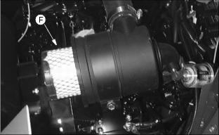
10. Install new primary element (F), push on securely.
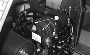
11. Install cover and engage latches (G).
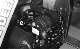
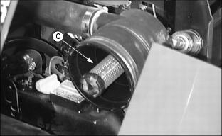
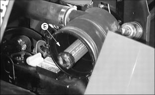
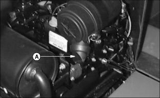
Clean Rubber Dust Unloading Valve
IMPORTANT: Avoid damage! Never operate engine without air cleaner elements and rubber dust unloading valve installed. |
Remove rubber dust unloading valve (A) and clean. Replace if damaged.
Service Cooling System Safely
Engine Coolant
IMPORTANT: Avoid damage! To prevent engine damage: · DO NOT use pure antifreeze or more than 50% antifreeze in the cooling system. · DO NOT mix or add any other type additives to the cooling system. |
Use ethylene glycol base coolant. These coolants usually have labels stating "For Automobile and Light Duty Service." These products are also often labeled for use in aluminum engines. Check container label before using.
Mix approximately 50 percent antifreeze with 50 percent distilled or deionized water. This mixture will provide freeze protection to -37 degrees C (-34 degrees F).
Certain geographical areas may require lower temperature protection. See the label on your antifreeze container or consult your John Deere distributor to obtain the latest information and recommendations.
The recommended antifreeze provides:
· Corrosion-resistant environment within the cooling system.
· Compatibility with cooling system hose and seal material.
· Protection during cold and hot weather operations.
Checking Coolant Level
· If engine is warm, coolant should be between lines (A) and (B) on coolant tank.
3. Remove cap (C) to add coolant.
4. If coolant is low, add ethylene glycol (without stop-leak additive) antifreeze and water in the ratio specified on the antifreeze container.
5. Install and tighten recovery tank cap.
6. Clean debris from air intake screen and radiator.
7. Check condition of hoses. Check for leaks or loose connections.
Draining Cooling System
1. Stop the engine and let it cool.
3. Slowly remove radiator cap (A).
4. Open radiator petcock (B). Drain coolant into a bucket.
5. After all coolant has drained, close radiator petcock.
6. Flush cooling system. (See Flushing Cooling System in this section.)
Flushing Cooling System
Turn radiator cap using a thick rag or glove to protect your hand. |
1. Fill cooling system with clean water and John Deere Cooling System Cleaner, or John Deere Cooling System Quick Flush or an equivalent. Follow directions on the can.

2. Install and tighten radiator cap (A).
3. Start and run engine until it reaches operating temperature. Stop engine.
4. Open radiator petcock (B) and drain the cooling system immediately before rust and dirt settle.
Filling Cooling System
1. Fill cooling system. For cold weather, use a solution of only ethylene glycol antifreeze (without a stop-leak additive) and clean, soft water. A chart on the antifreeze container tells how much antifreeze to use for the freeze protection needed in your area.
John Deere Cooling System Sealer or its equivalent may be added to the radiator to seal leaks. Do not use any other additives in the cooling system.
2. Install and tighten radiator cap.
3. Run engine until it reaches operating temperature.

5. After the engine cools, check coolant level in recovery tank (A). Level should be up to H mark (B) on tank when engine is hot or L mark (C) on tank when engine is cold.
6. Remove cap (D) to add coolant if necessary.
7. Check condition of coolant system hoses. Install new hoses periodically. Tighten hose clamps regularly.
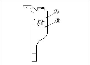
Checking Sediment Bowl
1. Stop the engine. Raise the hood.
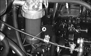
2. Check for water in sediment bowl (A): Orange ring will float on top of the water.
3. If necessary, clean bowl and replace filer. (See Cleaning Fuel Filter Sediment Bowl in this section).
Cleaning Fuel Filter Sediment Bowl
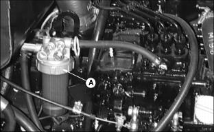
2. Turn collar (A) to remove bowl and filter. Discard the filter.
4. Install new filter and bowl.
Bleeding Fuel System
IMPORTANT: Avoid damage! DO NOT service injectors or injection pump. Special training and tools are required. See your John Deere distributor. |
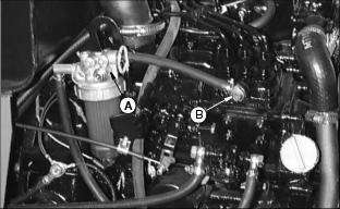
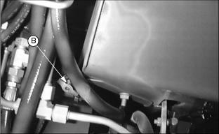
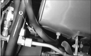
2. Loosen bleed screws (A) and (B).
3. Pump lever (C) until fuel flows from around screws.
4. Tighten screws when fuel flows free of bubbles.
6. If engine does not run smoothly, loosen three fuel line fittings (D) one at a time.