![]()
Introduction
Safety Signs
Controls
Operating
Operating Cutting Units
Replacement Parts
Service Machine Safely
Service Interval Chart
Service Lubrication
Service Engine
Service Transmission
Service Cutting Units
Service Electrical
Service Miscellaneous
Troubleshooting
Storing Machine
Assembly
Install Seat (Standard or Deluxe)
Install Front Roller and Lift Arm Assembly
Specifications
Warranty
John Deere Service Literature
John Deere Quality Statement
Copyright© Deere & Company

Assembly
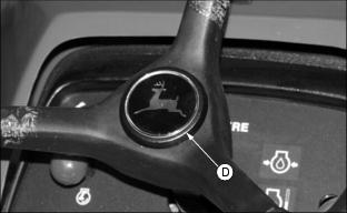
Install Steering Wheel
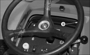
2. Install steering wheel (B).
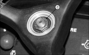
3. Install nut (C) and tighten.
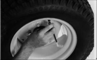
Install Tires
2. Remove wires from motors and mower.
3. Put a jack under frame and support machine.
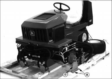
4. Remove bolts and nuts (A) holding shipping bracket (B) to pallet.
5. Remove lug bolts and shipping bracket. Retain hardware. Discard shipping bracket.
6. Raise machine and install front wheels. Tighten lug bolts to 40734 N·m (30025 lb-ft.).
8. Lower machine and remove jack.
Install Seat (Standard or Deluxe)
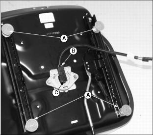
1. Remove threaded stud protectors (A) and plastic from seat.
2. Apply MPG2 grease to the seat switch harness connectors.
3. Connect the seat switch harness (B) to the seat switch (C).
4. Place loose seat switch harness connector through the frame hole (D) before placing threaded studs into the frame holes.
IMPORTANT: Avoid damage! Use caution when installing seat so that the four threaded studs of the seat do not scratch the painted surface of the frame. |
5. Carefully install seat so that the four threaded studs fit into the four holes (E) of the frame.
6. Locate the main wiring harness connector (F) under the machine frame and apply MPG2 grease.
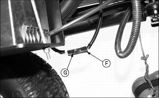
7. Connect the seat switch harness to the seat switch connector (G).
8. Install and tighten the four flange nuts to the threaded studs underneath the frame.
Remove Machine From Crating
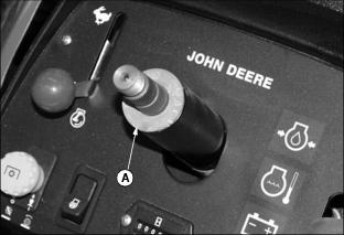
1. Engage the free-wheeling valve. (See Using The Free-Wheeling Lever in the Operating section.)
2. Carefully push the machine off the crating pallet.
Charge The Battery Safely
Follow instructions on the battery charger or in the charger operator's manual, or use the instructions below as a guide.
BEFORE YOU CHARGE THE BATTERY:
· Wait until the battery has warmed to room temperature. Do not charge a frozen battery.
· Check the electrolyte level of each cell. (See Checking Battery Electrolyte Level in this section.)
· Install the battery cap(s) on the battery.
Turn OFF and unplug the charger before you connect cables to the battery or disconnect cables from the battery.
If the battery becomes warm to touch during charging:
· Stop charging the battery until it cools.
Charging The Battery
NOTE: Make sure battery is fully charged at setup, the battery comes fully charged from the factory but some slight discharge may occur. Charge the battery to a minimum of 11.6 volts to ensure prolong battery life.
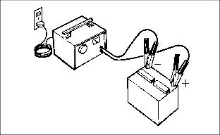
1. Remove and clean battery. (See Checking and Cleaning Battery this section).
2. Check electrolyte level. (See Checking Battery Electrolyte Level in this section.)
3. Leave cell caps on battery while you charge it.
4. Connect positive (+) charger cable to positive (+) battery terminal.
5. Connect negative (-) charger cable to negative (-) battery terminal.
7. Charge the battery. (See Charging Rates in Service - Electrical Section).
8. Unplug charger cord. Remove charger cables.
9. Install the battery. (See Replacing Battery in Service - Electrical section).
Install Front Roller and Lift Arm Assembly
1. Remove cap plugs from ends of roller shaft.
2. Insert grease zerks (A) in both ends.
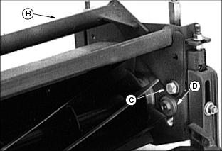
3. Install cutting unit yoke (B) using (C) 1/2 x 3 in. bolts, bushings (D), and nuts.
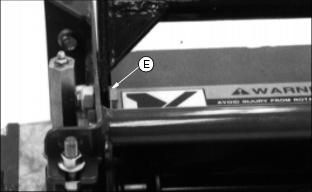
NOTE: There are two positions the yoke can be placed, float and fixed position (E), bolts and nuts provided. (See Cutting Shorter and Longer grass under Operating Cutting Units section).
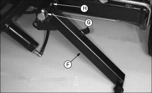
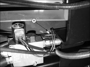
5. Install right and left front lift arms (F) onto mower using quick-lock pins (G).
6. Lubricate each respective lift arm fitting (H) with grease.
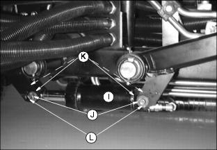
7. Install front hydraulic lift cylinder (I) as shown using drilled head pins (J), flanged bushings (K), and cotter pins (L).
8. Install cutting units (M) onto the respective lift arms using quick-lock pins (G).
NOTE: The yoke for the Left Front cutting unit is different and will have an "L" stamped on it to distinguish the offset to the motor side.
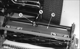
9. Lubricate individual cutting unit yoke fittings (N) with grease.
NOTE: The reel drive motors are installed on the inboard end of both front cutting units. For the Left Front position the cast end cap will have to be moved to the opposite end of the cutting unit before installing the drive motors.
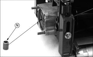
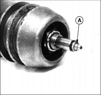
10. Put coupler (N) on motor reel shaft and install motor.
11. Repeat steps 1 through 7 on the other cutting units.
NOTE: Use the chart below to determine which coupler (N) you have.
Machines with serial number 40001 and above will use couplers with 11 teeth.
Adjust Lift Arm Bumper Stops
NOTE: Make this adjustment to prevent unnecessary movement of lift arms and cutting units during transport.
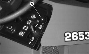
2. Pull Lift/Mow lever (A) back to raise lift arms and attached cutting units to a maximum raised position.
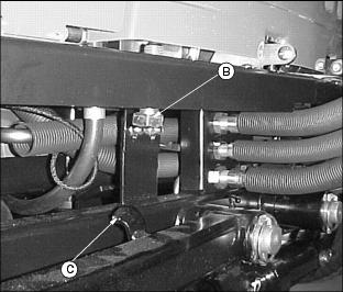
4. Locate adjustable lift arm bumper stop bolt (B) (one stop bolt for each cutting unit) mounted vertically under each side of the bumper.
5. Adjust bolts individually up or down to allow 3 mm (.12 in.) maximum lift arm movement at each stop (C).