![]()
Introduction
Product Identification
Safety
Operating
Replacement Parts
Service Intervals
Service Lubrication
Service Engine
Service Chain Case
Service Hydraulics
Service Steering & Brakes
Adjusting Auxiliary Hydraulic Control Handle Linkage
Adjusting Boom and Bucket Hand Control Linkage
Adjusting Angle of Boom and Bucket Foot Pedals
Service Electrical
Service Miscellaneous
Troubleshooting
Storage
Specifications
Warranty
John Deere Quality Statement
Service Record

Service Steering & Brakes
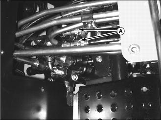
Adjusting Auxiliary Hydraulic Control Handle Linkage
NOTE: The auxiliary hydraulic hand control linkage goes down through the right control lever to the control valve.
1. Park machine safely. (See Parking Safely in the SAFETY section.)
2. Lock boom in the raised position.
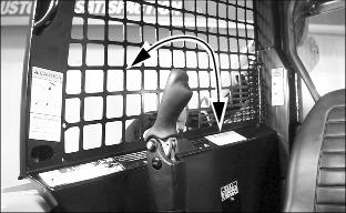
4. Move control lever handle all the way down and all the way up. Ensure that the valve locks into detent.
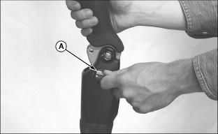
5. Confirm that when handle is returned to the neutral position, the locking mechanism (A) will engage without movement of the handle.
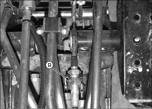
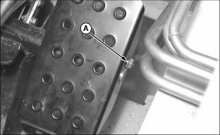
6. If necessary, adjust position of cable forward or backward using nuts (B) to properly position the handle.
7. Install center cover plate and lower boom to ground.
Adjusting Boom and Bucket Hand Control Linkage
1. Park machine safely. (See Parking Safely in the SAFETY section.)
2. Lock boom in the raised position.
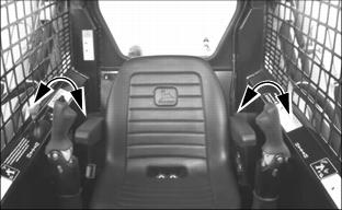
4. Move each control lever handle all the way down and all the way up. Ensure that boom control valve locks into detent.
5. Confirm that when handles are returned to the neutral position, they are in the center of the operating range.
6. If necessary, adjust positions of cables forward or backward using nuts (A) to properly position handles.
7. Install center cover plate and lower boom to ground.
Adjusting Angle of Boom and Bucket Foot Pedals
The angle of the foot pedals can be adjusted to suit different operators or different footwear which affects foot position.