![]()
Introduction
Product Identification
Safety
Operating
Adjusting Suspension Seat (Optional)
Testing Boom And Bucket Interlock System
Cab Enclosure With Wiper (Optional)
Using the Windshield Wiper Switch
Entering and Exiting Skid Steer
Auto Preheat Module (Optional)
Dual Flasher Switch (Optional)
Heater/Defroster Switch and Thermostat (Optional)
Attaching Auxiliary Hydraulic Lines
Attaching Hydraulic Lines Between Attachments and Skid Steer
Attaching High-Flow Hydraulic Lines
Using Auxiliary Hydraulic Control Handle
Boom and Bucket Hand Controls (Optional)
Using Auxiliary Foot Pedal Lockout (If Equipped)
Using QUIK-TATCH Attachment Mounting System
Returning the Bucket to the Loading Position
Transporting Skid Steer on a Trailer
Replacement Parts
Service Intervals
Service Lubrication
Service Engine
Service Chain Case
Service Hydraulics
Service Steering & Brakes
Service Electrical
Service Miscellaneous
Troubleshooting
Storage
Specifications
Warranty
John Deere Quality Statement
Service Record

Operating
Daily Operating Checklist
o Check hydraulic oil level and hoses.
o Check coolant level and hoses.
o Remove dirt and debris from radiator.
Operator Station

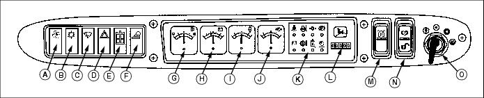
B - Air Conditioner (Optional)
C - Windshield Wiper (Optional)
D - Hazard Warning Lights (Optional)
Warning Lights (K)
F - Hydraulic Over Temperature
G - Hydraulic Filter Restriction
Adjusting Seat

2. Slide seat forward or backward to desired position. Release lever.
Adjusting Suspension Seat (Optional)
1. Adjust lever (A) for the appropriate operator body weight. The lever has three positions:
· Up - for lighter weight operators.
· Center - for medium weight operators, and
· Down - for heavier weight operators.
2. Adjust lever (B) for the appropriate back seat angle:
· Turn the lever counterclockwise to angle seat forward.
· Turn the lever clockwise to angle seat back.
Testing Safety Systems
NOTE: If the skid steer is equipped with auxiliary hydraulics be sure the control valve is in neutral. The park brake switch must be engaged before engine will crank.
Use the following checkout procedure to check for normal operation of machine.
If there is a malfunction during one of these procedures, Do not operate machine. See your John Deere dealer for service.
Perform these tests in a clear open area. Keep bystanders away.
Testing Park Brake Switch
1. Park machine safely. (See Parking Safely in the SAFETY section.)
2. Sit on operator's seat, buckle seat belt, and disengage park brake switch.
3. Turn the key to the start position.
Testing Boom And Bucket Interlock System
1. Park machine safely. (See Parking Safely in the SAFETY section.)
2. Sit on operator's seat, buckle seat belt, and engage park brake switch.
4. Run engine at maximum engine speed.
5. Place park brake switch in the middle (run) position.
6. Push down on the back of boom control pedal to slowly raise boom. Release pedal. Push down on the back of bucket control pedal to slowly curl bucket. Release pedal.
7. Unbuckle seat belt. Move pedals.
The operator must complete the following sequence, to release the boom and bucket:
3. Disengage the park brake switch.
Testing Seat Switch
1. Park machine safely. (See Parking Safely in the SAFETY section.)
2. Sit on operator's seat, buckle seat belt, and engage park brake switch.
4. Disengage park brake switch.
5. Raise up off the seat, but do not unbuckle seat belt or get out of skid steer.
Testing Seat Belt Switch
1. Park machine safely. (See Parking Safely in the SAFETY section.)
2. Sit on operator's seat, buckle seat belt, and engage park brake switch.
4. Disengage park brake switch.
5. Unbuckle the seat belt, but do not get out of skid steer.
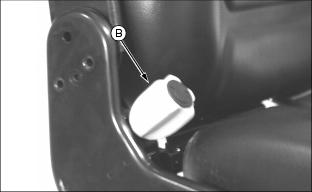
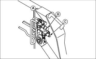
Demolition Door (Optional)
The demolition door offers protection from flying debris commonly found on work sites. A demolition door is required when operating a Worksite Pro Hydraulic Breaker.
The demolition door contains a safety interlock switch that will not release when the door is open.
The seat belt indicator light will go out after the proper skid steer starting sequence is followed and the demolition door is securely closed. If the seat belt indicator light does not go out, open and close the demolition door securely.
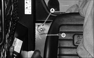
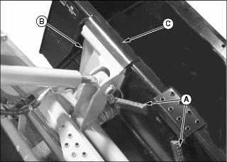
To Open the Door:
· Turn the handle (A) and slide the door up into the operator's station.
To Close the Door:
· If you are located outside the skid steer, pull down on handhold (C) until door latches into place. If you are located inside the skid steer, pull down on handholds (B) until door latches into place.
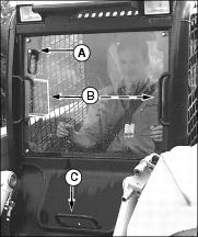
Cab Enclosure With Wiper (Optional)
The cab enclosure with wiper offers protection from flying debris and inclement weather.
The cab enclosure door contains a safety interlock switch that will not release when the door is opened.
The seat belt indicator light will go out after the proper skid steer starting sequence is followed and the cab enclosure door is securely closed. If the seat belt indicator light does not go out, open and close the cab enclosure door securely.
To Open the Door:
IMPORTANT: Avoid damage! To prevent damage to the wiper arm, always turn off the windshield wiper before opening the cab enclosure door. |
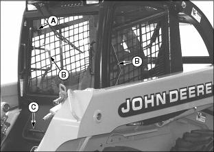
· Turn the handle (A) and slide the door up into the operator's station.
To Close the Door:
· If you are located outside the skid steer, pull down on handhold (C) until door latches into place. If you are located inside the skid steer, pull down on handholds (B) until door latches into place.
Using the Windshield Wiper Switch
NOTE: The key switch must be in the accessory or run position and cab enclosure door must be shut to operate the windshield wiper.
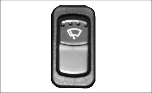
The windshield wiper switch is a three position switch:
· The momentary up position releases windshield washer fluid.
· The middle position turns the windshield wiper on.
· The down position turns the windshield wiper off.
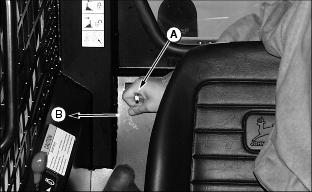
Entering and Exiting Skid Steer

To enter the skid steer from the side or the front without a bucket attached:
· Use the boom step (A) and handholds (B) and (C).
To enter the skid steer from the front with a bucket attached:
· Use step (D) on back of bucket and handholds (B) and (C).
To enter the skid steer when the boom is raised on the boom locks:
3. Step over the toe guard shielding (E).
To exit the skid steer:
2. Use the handholds for support and step onto the boom step or bucket step and then onto the ground.
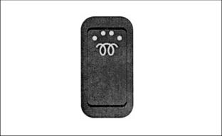
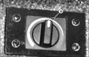
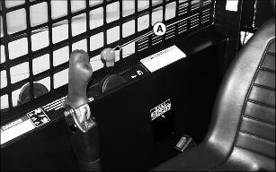
Using the Park Brake Switch
The park brake is applied when any of the following occur:
· The operator is out of the seat.
· The seat belt is not buckled.
· Park brake switch is in the up position.
· Park brake switch is in the middle position but has not yet been cycled through the momentary down position.
· There is no hydraulic charge pressure.
Engaging the Park Brake Switch:

· Push up on top portion (A) of rocker switch. This position also hydraulically locks the boom and bucket.
· To hydraulically enable the boom and bucket, while the park brake is locked, push rocker switch to the middle position.
Disengaging the Park Brake Switch:
NOTE: The engine must be running.
1. The operator must sit in seat and then fasten the seat belt.
2. Push rocker switch to the momentary down position (B) and release to middle position.
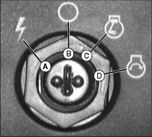
Using the Cold Start Switch
The cold start switch controls an air intake preheater to assist in cold weather starting.
Starting fluid is highly flammable; do not use starting fluid. An electric air preheater may ignite starting fluid. |
Turn the key switch to the run position. Push and hold the cold start switch using the following table:
*Add 5 seconds for every 2 change in temperature (10 C to 0 C).
After allotted time, turn key switch to the start position.
Auto Preheat Module (Optional)
With the automatic air preheater option, the momentary cold start switch is replaced by a "wait" lamp. Turn the key switch to the run position. Wait until the "wait" lamp goes out before turning the key switch to the start position. The air preheater timing is automatic per the following table:
Block Heater (Optional)
The block heater allows for quick starts and warm-ups during very cold weather.

1. Plug block heater (A) into a 110-volt outlet when skid steer is not in use and the heater will keep the engine coolant at a warm temperature.
2. Unplug the block heater from outlet.
Backup Alarm (Optional)
The backup alarm becomes functional whenever the key switch is in the accessory or run position. Switches located on the steering plates detect movement in the drive control levers and will sound an audible alarm whenever the skid steer is operated in reverse.
Dual Flasher Switch (Optional)
NOTE: The key switch must be in the accessory or run positions to activate dual flashers.

The dual flasher switch activates flashing lights to alert other bystanders and vehicles that the skid steer is in the area and is operational. The dual flasher switch is a two position switch:
Work Light Switch
NOTE: The key switch must be in the accessory or run positions to operate lights.
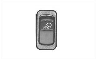
The work light switch is a three position switch:
· The up position turns on the front work lights, red tail lights, and rear work light.
· The middle position turns on the front work lights and red tail lights.
· The down position turns all lights off.
High-Flow Switch (Optional)
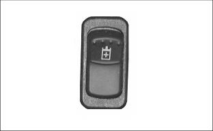
The high-flow option is for attachments that require a high hydraulic flow rate to operate. The high-flow switch is a three position switch:
· The momentary up position is on and will release to the middle run position. Push up to activate high-flow option and release to the middle run position.
NOTE: If skid steer engine is shut down, the switch must be recycled to enable high-flow.
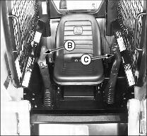
Heater/Defroster Switch and Thermostat (Optional)
NOTE: The key switch must be in the run position with the engine running to generate heat from the heater/defroster.
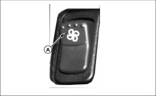
The heater/defroster switch (A) activates the flow of warm air into the operator's station to keep the operator comfortable and windows free of moisture during inclement weather. The heater/defroster switch is a two position switch:
The thermostat (B) controls the temperature of the heated air forced into the operator's station:
· For warmer air, turn thermostat to the right.
· For cooler air, turn thermostat to the left.
Using the Key Switch
The key switch has four positions.
IMPORTANT: Avoid damage! The battery may lose its charge if the key switch is left in the Accessory position for an extended period of time. |
Starting the Engine
1. Sit in the seat, adjust and fasten the seat belt.
2. Be sure all drive and auxiliary hydraulic controls are in neutral.
3. Engage the park brake switch.

4. Push throttle lever (A) forward to 1/3 throttle position.
5. Turn key to the run position, but do not crank engine.
· The engine low oil pressure LED will be lit until the engine starts.
To start the engine in extremely cold conditions, see Using Cold Start Switch in this section.
Starting fluid is highly flammable; do not use starting fluid. An electric air preheater may ignite starting fluid. |
7. Turn key to the start position. Release key when engine starts. If the engine does not start within 30 seconds, allow the starter to cool for one minute before trying to start it again (turn the key to the off position).
· A warning light bulb check is performed each time the skid steer is started.
IMPORTANT: Avoid damage! To prevent damage of hydraulics and engine in temperatures below 0°C (32°F), run at slow idle for ten minutes before operation of controls. |
· Always allow the engine to warm up before applying a load.
Using Boom Locks
The boom locks are used whenever you need to leave the machine with the boom in a raised position.
To Lock Boom In The Raised Position:
1. Park machine safely. (See Parking Safely in the SAFETY section.)
3. Using boom pedal, raise boom a short distance above boom locks.
4. Slide lever (A) away from the seat to extend boom locks to the locked position (B).
5. Using boom pedal, slowly lower boom onto locks (C).
To Disengage Boom Locks:
1. Using boom pedal, raise boom a short distance off of locks.
2. Slide lever (A) toward seat to retract the boom locks to the unlocked position (B).
3. Using boom pedal, slowly lower boom and attachment to the ground.
Stopping the Engine
1. Return the drive controls to the neutral position to stop the skid steer.
2. Return auxiliary control handle to the neutral position.
3. Pull the throttle lever back to about the half-speed position.
4. Lower the boom completely to the ground. If the boom is to remain in the raised position use the boom locks.
5. Engage the park brake switch.
6. Pull the throttle lever back to the idle position.
NOTE: Extended periods of engine idling is inefficient and should be avoided except when necessary.
7. Turn key to the off position.
Using Drive Control Levers
1. Before driving machine, lower the boom. If the boom is locked in the raised position, disengage the boom locks.
2. Push throttle lever (A) all the way forward to the full throttle position.
3. Disengage the park brake switch.
NOTE: Right lever (B) controls right drive wheels, and left lever (C) controls left drive wheels:
4. Activate the control levers:
· Push both levers forward at the same time to go forward.
· Pull both levers back at the same time to go backward.
· Push one lever forward and pull the other lever backward at the same time to make a short turn.
· Slowly return levers to the middle (neutral) position to stop.
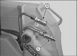
Attaching Auxiliary Hydraulic Lines
To Relieve Hydraulic Line Pressure
3. Turn key switch to the run position - do not start engine.
4. Move auxiliary control handle left and right a few times.
To Attach Hydraulic Lines

1. Pull back on outer knurled ring (A) and push couplers together with a firm continuous motion until couplers lock into place.
To Remove Hydraulic Lines
1. Relieve hydraulic line pressure before removing hydraulic auxiliary lines.
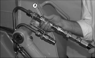
2. Push hydraulic line in while pulling back on outer knurled ring (A). The coupler will unlock and hydraulic line can be removed.
Attaching Hydraulic Lines Between Attachments and Skid Steer
1. Park machine safely. (See Parking Safely in the SAFETY section.)
IMPORTANT: Avoid damage! To prevent hydraulic lines from being pinched, be sure hoses rest between step and skid steer torque tube. |
2. Install quick-disconnect couplers on attachment hoses to quick-disconnect couplers on skid steer.
3. Enter skid steer, fasten seat belt, and start engine.
4. Slowly cycle the auxiliary control handle several times to purge system of air and check for proper hydraulic connection.
5. With the attachment in a static position, check the hydraulic oil level of the skid steer. Fill to operating level as necessary.
Attaching High-Flow Hydraulic Lines
Attach high-flow hydraulic lines as indicated above.
Using Auxiliary Hydraulic Control Handle
The auxiliary hydraulic control handle directs hydraulic oil flow to operate different functions on a variety of attachments. The function may be different depending on the attachment being used and the way the hydraulic lines have been connected.
Unlocking Handle From Neutral Position

Locking Handle In Neutral Position
Activating Auxiliary Hydraulics:
· Pivot handle (B) down toward seat to supply oil to the male quick coupler (C).
· Pulling the handle all the way down toward the seat will put the control valve into detent position to give continuous oil flow to an attachment. The handle will stay in this position until the operator moves the handle.
· Pivot the handle up away from seat to supply oil to the female quick coupler (D), reversing oil flow.
IMPORTANT: Avoid damage! The hand control must be locked in neutral when the auxiliary hydraulics are not in use to prevent overheating of hydraulic oil. |
NOTE: If the handle hasn't been moved all the way down into the detent position, it will automatically return to the center position when the operator lets go and will stop oil flow to the auxiliary couplers.
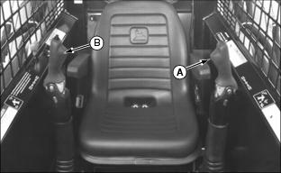
Using Boom Pedal
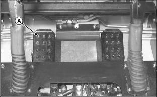
Left Pedal (A) Controls the Boom:

· Push back of pedal down to raise boom.
· Push front of pedal down to lower boom.
· Boom will move faster the farther you push the pedal down.
· Pedal will return to neutral-hold position when you release if not in the float position.
Float Position:
Relieves the down pressure on the boom cylinders and allows the boom and attachment to float with the contour of the ground.

· Push front of boom pedal down into the detent to engage float. Boom will stay in float until you push down rear of pedal.
NOTE: If your unit is equipped with the optional Boom and Bucket Hand Control option, the left pedal is non-functional. See Boom and Bucket Hand Controls in this section.
Using Bucket Pedal

Right Pedal (B) Controls the Bucket:

· Push back of pedal down to roll bucket back.
· Push front of pedal down to dump bucket.
· Bucket will move faster the farther you push the pedal down.
· Pedal will return to neutral-hold position when you release it.
NOTE: If your unit is equipped with the optional Boom and Bucket Hand Control option, the right pedal becomes the auxiliary hydraulics control. See Boom and Bucket Hand Controls in this section.
Boom and Bucket Hand Controls (Optional)
NOTE: The left pedal is non-functional. The right pedal is the Auxiliary Hydraulics Control.
Activating the Boom Controls Using Left Control Handle (A):
· Pull handle up toward ROPS to raise boom.
· Push handle down toward seat to lower boom.
· Boom will move faster the farther you move the handle.
· Push handle down towards seat and into the detent position to engage float.
Right Control Handle (B) Controls Bucket:
· Push handle down toward seat to roll bucket back.
· Pull handle up toward ROPS to dump bucket.
· Bucket will move faster the farther you move the handle.
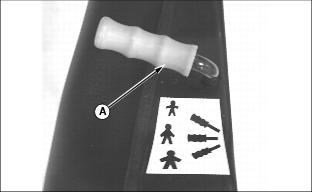
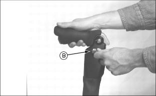
Using Auxiliary Foot Pedal Lockout (If Equipped)
Unlocking Right Pedal (Auxiliary Hydraulics Control):

Picture Note: This handle (A) is located in front of the right steering lever.
· Push the auxiliary foot pedal lockout handle (A) forward and rest in notch (B).
Locking Right Pedal (Auxiliary Hydraulics Control) In Neutral Position:
· Pull the auxiliary foot pedal lockout handle (A) rearward as shown in previous photo.
Activating Auxiliary Hydraulics:

· Push the front of the right foot pedal down at (C) to supply oil to the male quick coupler (D).
· Pushing the front of the right foot pedal down into detent will put the control valve into the detent position to give continuous oil flow to an attachment. The pedal will stay in this position until the operator releases the pedal.
· Push the back of the right foot pedal to supply oil to the female quick coupler (E) reversing oil flow.
IMPORTANT: Avoid damage! The auxiliary foot pedal lockout must be locked in neutral when the auxiliary hydraulics are not in use to prevent overheating of hydraulic oil. |
NOTE: If the pedal has not been locked into the detent position, it will automatically return to the center position when the operator does not apply pressure to the pedal and will stop oil flow to the auxiliary couplers.
Self Leveling (Optional)
If the skid steer is equipped with the self leveling option the QUIK-TATCH mounting plate and/or attachment (i.e.: bucket) will remain in the same relative position to the ground throughout the lift cycle.
Example:
If the bucket is level at the start of the lift cycle, it will maintain its level position throughout the cycle.
· Self leveling is only operational during the lift cycle.
· To override the self leveling feature, use the bucket pedal or hand control (if equipped).
· If you wish to disable the self leveling feature contact your Authorized John Deere Skid Steer Dealer.
Using Emergency Exit
The rear window can be removed to provide an exit in the event the front exit is blocked.
Push on the bottom right corner of the window to force the window out from the molding.
Using QUIK-TATCH Attachment Mounting System
· DO NOT try to latch or unlatch handles from the cab. · Be careful not to pinch hands between latch handle and step or latch handle and attachment. |
Installing Attachment:
1. Park machine safely. (See Parking Safely in the SAFETY section.)
2. Lift latch handles (A) up to the unlatched position. Be sure the latch handles are all the way up so the lock pins are fully retracted.
3. Enter skid steer, fasten seat belt, start the engine, and disengage park brake switch.
4. Tilt mounting plates (B) forward.
5. Drive forward, raise boom, and guide the top of the mounting plates under the attachment mounting brackets (C).
6. Raise and roll back the mounting plates. The back of the attachment should rest against the front of the mounting plate.
7. When the attachment is fully supported, lower the boom until the boom is resting on the boom stops.
8. Roll the attachment out, stopping with the bottom edge of attachment about 50 mm (2 in.) from the ground.
9. Engage the park brake switch, turn off the engine, and exit the skid steer.

10. Push the two latch handles (A) down to lock the attachment to the QUIK-TATCH.
11. Enter the skid steer, fasten the seat belt, start the engine, and disengage the park brake switch.
12. Activate the lift cylinders to raise attachment and extend bucket cylinders to tilt attachment at a slight downward angle so that the bottom of the QUIK-TATCH is visible.
13. Visually inspect the attachment mechanism to verify that pins are fully engaged in slots on the back of the attachment.
14. Connect hydraulic hoses if attachment is so equipped.
Removing Attachment:
1. Park machine safely. (See Parking Safely in the SAFETY section.)
2. Disconnect hydraulic hoses from attachment if so equipped.
3. Pull the latching handles up to the unlatched position to release the pins from the lower attachment tabs. Be sure the latch handles are fully raised.
4. Enter skid steer, fasten seat belt, start the engine, and disengage park brake.
5. Lower attachment so that it rests securely on the ground.
6. Tilt the mounting plate forward and back the skid steer away from the attachment at the same time.
Filling the Bucket
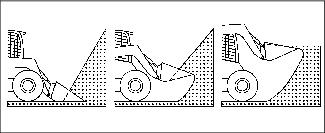
There are two basic methods of filling a bucket from a pile - Arc Penetration and Step Penetration. Judge the type of penetration needed for loading and vary the methods to suit the materials.
Arc Penetration
With the arc penetration method, the bucket is forced into the pile and rolled back while raised in a continuous upward arc until the bucket is filled. When activating both the lift and bucket hydraulic circuits at the same time, the lift or roll-back system may occasionally stall. When this happens, disengage either the lift or roll-back function to allow maximum hydraulic force to one set of the cylinders.
Step Penetration
With the step penetration method, the bucket is forced into the pile at ground level with the bucket bottom horizontal to the ground. Force the bucket into the pile as far as possible during the initial thrust. Raise the bucket about a foot and then force it further into the pile. Repeat this cycle as many times as necessary to fill the bucket.
NOTE: If the engine pulls down as the skid steer is engaging a load, the directional controls are being held too far in the direction of travel. Maximum torque is obtained at minimum ground speed.
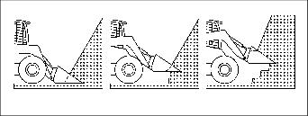
Digging
When digging with the skid steer, remove a thin layer with each pass. This method is efficient and minimizes wheel slippage. When encountering firmly packed materials, flutter the bucket control valve to assist penetration. Teeth can be installed on the bucket to provide better penetration.
Returning the Bucket to the Loading Position
Immediately after the bucket has been fully dumped, begin the roll-back cycle as the machine is backed away from the dump site. Repositioning the bucket for the filling cycle while the boom is lowering is a good time saver. Fine adjustments in bucket position can be made as the skid steer begins forward on the filling cycle, thereby saving a period of dead time between the dumping and filling cycles.
Bulldozing with the Bucket
|
· Do not push against objects with the boom fully raised or damage to the boom or boom cylinders may occur. · Do not push forward with the bucket fully dumped as the bucket cylinders may be damaged. |
The skid steer can be used for bulldozing by controlling the tilt of the bucket.
The skid steer can be used for leveling by placing the bucket in the dump position and backdragging loose soil. The tilt of the bucket will control the amount of soil that is transported.
Place the boom control valve spool in the detent (float) position to allow the bucket to follow the ground contour and deposit soil in the low areas.
Dislodging the Machine
In most cases, when a machine becomes bogged down, the bucket can be used to push the skid steer to more solid ground:
· Raise the boom and tilt the bucket forward so that the cutting edge contacts the ground.
· Curl the bucket and lower the boom (maintain contact with the ground) while pulling evenly rearward on the control levers.
· Repeat this cycle as many times as necessary to move the machine to solid ground.
Transporting Loaded Bucket
Never transport a loaded bucket at full height. Keep the bucket as low to the ground as possible for better stability.
When backing out and transporting a load, raise the bucket just high enough to clear obstacles in your path. Raising a loaded bucket too high reduces stability.
Worksite Layout
For an efficient operation, arrange the job to minimize the time required to perform the work cycle.
When selecting the dump site, consider wind direction and ground slope. Whenever possible, position the dump site so that the wind will carry dust away from the operator.
Before the work cycle begins, clear worksite of unauthorized personnel. Take a few minutes to level off the work area if it is not smooth.
Minimize transport distances for a fast work cycle.
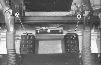
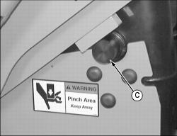
Transporting Skid Steer on a Trailer
IMPORTANT: Avoid damage! Never put chains across the boom or bucket cylinders. Damage to the cylinders may occur. |
Use a heavy-duty trailer to transport your machine.
When loading machine onto a truck or trailer, keep the boom and/or attachment down. Back skid steer onto a trailer. Before exiting the skid steer, lower the attachment to the trailer bed, engage the park brake switch and shut off the engine.

Picture Note: Bucket removed for photo clarity
Fasten machine to trailer with heavy-duty straps, chains, or cables using tie down (A) in front, and (B) in the rear. Both front and rear straps must be directed down and outward from machine. Trailer must have signs and lights required by law.
Craning the Skid Steer
A kit is required to crane the skid steer. See your Authorized John Deere Skid Steer Dealer to order kit. Follow the instructions supplied with the kit.