![]()
Introduction
Product Identification
Safety
Operating
Replacement Parts
Service Intervals
Service Lubrication
Service Engine
Changing Engine Oil and Filter
Cleaning Radiator and Oil Cooler Fins
Replacing Primary Air Cleaner Element
Replacing Secondary Air Cleaner Element
Checking and Adjusting Fan Belt
Draining Fuel/Water Separator Filter
Changing Fuel/ Water Separator Filter
Service Chain Case
Service Hydraulics
Service Steering & Brakes
Service Electrical
Service Miscellaneous
Troubleshooting
Storage
Specifications
Warranty
John Deere Quality Statement
Service Record

Service Engine
Avoid Fumes
Engine Oil
Use oil viscosity based on the expected air temperature range during the period between oil changes.
The following oil is preferred after first 100 hours of break-in oil is used:
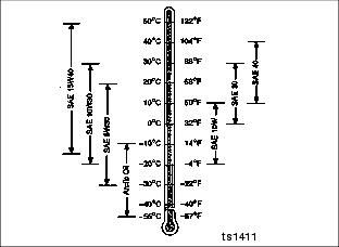
· John Deere TORQ-GARD SUPREME or TORQ-GARD PLUS-50
Other oils may be used if they meet one of the following:
· API Service Classification CE
· API Service Classification CD
If John Deere TORQ-GARD SUPREME or TORQ-GARD PLUS-50 engine oil and a John Deere oil filter are used after first 100 hours, the oil and filter service interval may be extended by 50%.
If diesel fuel exceeding 0.5% sulfur content is used, reduce the service interval for engine oil and filter by 50%.
Oils meeting Military Specification MIL-L-46167B may be used as arctic oils.
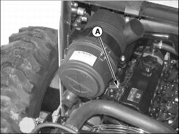
Checking Engine Oil Level
1. Park machine safely. (See Parking Safely in the SAFETY section.)
2. Open rear service door and engine cover.
NOTE: Add less than one quart if oil level measures to mark at (B).
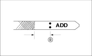
4. Oil level should be between the ADD and full mark. Add oil if necessary.
Changing Engine Oil and Filter
1. Park machine safely. (See Parking Safely in the SAFETY section.)
2. Run engine a few minutes to warm oil.
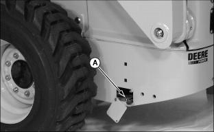
5. To locate engine oil drain hose (A), remove access cover on left side of skid steer.
6. Remove plug using two wrenches to avoid twisting the hose. Allow oil to drain into a suitable container.
NOTE: Make sure O-ring is still intact when installing hose plug.
8. After oil has drained, install hose plug.
9. Open rear service door and engine cover.
10. Remove left side engine panel.
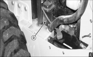
11. Clean dirt or debris from around engine oil filter (B). Remove oil filter using a filter wrench. Turn filter counterclockwise.
12. Apply a film of clean engine oil on seal of new filter.
13. Install filter. Turn filter until seal contacts mounting surface. Then turn filter by hand 1/2 turn more.
NOTE: Rocker arm cover in photo may be reversed depending upon skid steer model.

14. Remove engine oil fill cap (C).
15. Add oil through fill cap with John Deere TORQ-GARD SUPREME or TORQ-GARD PLUS-50. Engine oil capacity is 6.5 L (6.9 qt.).
17. Install and tighten fill cap.
18. Start engine and run at slow speed for two minutes. Check for leaks around filter and drain plug.
20. Install access cover removed earlier. Tighten access cover cap screws.
21. Install left side engine panel, close engine cover, and rear service door.
Cleaning Radiator and Oil Cooler Fins
1. Park machine safely. (See Parking Safely in the SAFETY section.)
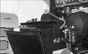
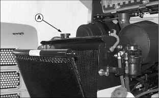
3. Lift upper two latches (A) from oil cooler (one on each side). Pivot oil cooler out and away from radiator.
4. Clean radiator fins and cooler fins using compressed air.
5. Clean any dirt build-up in the engine area.
6. If any areas require washing after cleaning with air, allow radiator and cooler parts to dry thoroughly before operating skid steer.
7. Pivot oil cooler into position and secure with latches (A).
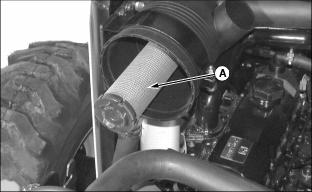
Replacing Primary Air Cleaner Element
1. Park machine safely. (See Parking Safely in the SAFETY section.)
2. Open rear service door and engine cover.
3. Remove left side engine panel.
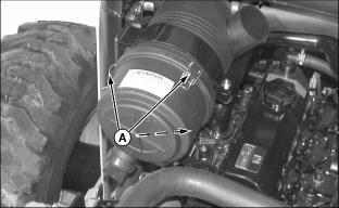
4. Unhook three end cap latches (A) and remove end cap.
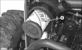
5. Remove and discard primary element (B).
6. Clean any loose dirt from the canister and inspect the end of the canister for dirt that may prevent the new element from sealing properly.
7. Install new primary element.
8. Install cover and secure with three latches.
9. Start engine and check air restriction indicator to be sure there is no restriction.
· If air restriction indicator still shows restriction, replace secondary element.
10. Install left side engine panel, close engine cover, and rear service door.
Replacing Secondary Air Cleaner Element
1. Park machine safely. (See Parking Safely in the SAFETY section.)
3. Remove secondary element (A). Discard element.
6. Install cover and secure with three latches.
7. Start engine and check air restriction light on the instrument panel to be sure there is no restriction.
· If restriction indicator light is still on, see your Authorized John Deere Skid Steer Dealer.
8. Install left side engine panel, close engine cover, and rear service door.
Recommended Engine Coolant
The following John Deere coolants are preferred:
· COOL-GARD PRE-DILUTED SUMMER COOLANT (TY16036).
· COOL-GARD CONCENTRATED SUMMER COOLANT (TY16034).
If neither of the recommended coolants is available, use a glycol base coolant that meets the following specification:
Check container label before using to be sure it has the appropriate specifications for your machine. Use coolant with conditioner or add conditioner to coolant before using.
If using concentrate, mix approximately 50 percent antifreeze with 50 percent distilled or deionized water before adding to cooling system. This mixture will provide freeze protection to -37 degrees C (-34 degrees F).
Certain geographical areas may require lower temperature protection. See the label on your antifreeze container or consult your John Deere dealer to obtain the latest information and recommendations.
Liquid Coolant Conditioner
The skid steer is designed with a wet sleeve block engine. John Deere Liquid Coolant Conditioner may be added for additional protection against rust and corrosion in the engine and to protect the cooling system. Other conditions may be used is they contain non-chromate inhibitors. Follow directions on the container.
Checking Coolant Level
1. Park machine safely. (See Parking Safely in the SAFETY section.)
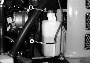
4. Check recovery tank coolant level. Coolant should be, at least, to the Add mark (A) on the tank.
5. Remove tank cap (B) if necessary to add coolant.
6. Install and tighten tank cap.
Service Cooling System
Draining Cooling System
1. Park machine safely. (See Parking Safely in the SAFETY section.)
3. Open rear service door and engine cover.
5. Slowly remove radiator cap (A).
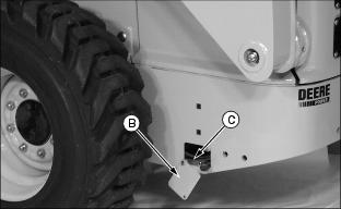
6. Remove access cover (B) on the left side of skid steer and locate coolant drain hose (C).
7. Open drain valve (D) and allow coolant to drain into a suitable container.
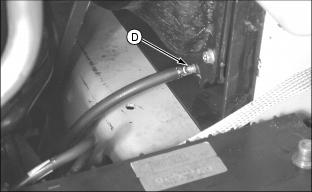
8. After coolant has drained, close radiator drain valve (D).
Flushing Cooling System
1. Fill cooling system with clean water and John Deere Cooling System Cleaner, John Deere Cooling System Quick Flush or an equivalent recommended for aluminum engines. Follow directions on the can.

2. Install and tighten radiator cap (A).
3. Start and run engine until it reaches operating temperature.
5. Drain cooling system immediately before rust and dirt settle.
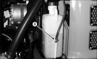
· Remove spring clip (B) to remove overflow hose from tank.
8. Install tank and overflow hose.
Filling Cooling System
NOTE: John Deere COOL-GARD coolant is recommended when adding new coolant to the cooling system.
Follow the directions on the container for correct mixture ratio.
When operating engine in extremely cold temperatures, see your Authorized John Deere Skid Steer Dealer.
3. Check condition of coolant system hoses. If new hoses are needed, contact your Authorized John Deere Skid Steer Dealer.
4. Fill cooling system. Cooling system capacity is 9.5 L (10 qt).
5. Install and tighten radiator cap.
6. Start engine and run until engine reaches operating temperature.
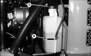
8. Check recovery tank coolant level, it should be at or above the Add level.
9. Remove cap (B) from recovery tank to add coolant if necessary. Install cap.
10. Tighten hose clamps as necessary.
Checking and Adjusting Fan Belt
1. Park machine safely. (See Parking Safely in the SAFETY section.)
2. Open rear service door and engine cover.
IMPORTANT: Avoid damage! To prevent damage to alternator, disconnect negative (-) battery cable when adjusting or replacing belt. |
3. Remove left side engine panel.

4. Press lightly in the center of belt (A) between alternator and fan pulleys. Belt should deflect approximately 3 mm (1/8 in.).
5. Replace belt if worn or damaged.
· Disconnect negative (-) battery cable.
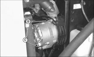
· Loosen nuts (B) and (C) on alternator.
· Pivot alternator toward engine to loosen belt, and away from engine to tighten belt.
9. Install left side engine panel, close engine cover, and rear service door.
Replacing In-Line Fuel Filter
1. Park machine safely. (See Parking Safely in the SAFETY section.)
2. Open rear service door and engine cover.
3. Remove right side engine panel.

4. Disconnect electrical connector (A).
5. Loosen and slide hose clamps (B) away from fuel filter. Remove hoses.
8. Install hose and tighten clamps.
9. Connect electrical connector (A).
10. Install side panel, close engine cover, and rear service door.
Draining Fuel/Water Separator Filter
1. Park machine safely. (See Parking Safely in the SAFETY section.)
2. Open rear service door and engine cover.
3. Remove right side engine panel.
4. Place a small container under fuel/water canister.
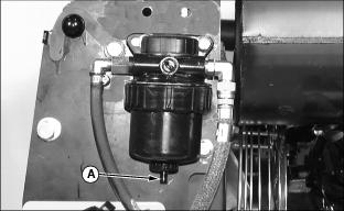
5. Loosen valve (A) to drain fuel.
6. When fuel/water has stopped draining, tighten valve (A).
7. Dispose of fuel/water properly.
8. Close engine cover, and rear service door.
Changing Fuel/ Water Separator Filter
1. Park machine safely. (See Parking Safely in the SAFETY section.)
2. Open rear service door and engine cover.
3. Remove right side engine panel.

4. Drain fuel/water separator.
5. Rotate canister retaining ring (A) counterclockwise to remove canister (B).
6. Insert new canister by aligning location tabs and pushing up to seat canister. Tighten retaining ring clockwise by hand.
7. Close engine cover and rear service door.
Priming Fuel System
The fuel system utilizes an automatic priming system.
To ensure that the fuel system is primed, turn the key switch to the run position and wait twenty (20) seconds before starting the engine.