![]()
Introduction
Product Identification
Safety
Operating
Replacement Parts
Service Intervals
Service Lubrication
Service Engine
Service Chain Case
Service Hydraulics
Service Steering & Brakes
Service Electrical
Checking Battery Electrolyte Level (Maintenance Type Batteries Only)
Replacing Work Light Bulb (Front or Rear)
Service Miscellaneous
Troubleshooting
Storage
Specifications
Warranty
John Deere Quality Statement
Service Record

Service Electrical
Battery
Cleaning or Replacing Battery
NOTE: It is not necessary to raise boom arms onto boom locks to remove the battery however, doing so will improve accessibility to the battery.
2. Park machine safely. (See Parking Safely in the SAFETY section.)
3. Lock boom in the raised position.
4. Stop engine and engage park brake.
5. Open rear service door and engine cover.
6. Remove left side engine panel.
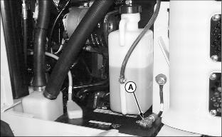
7. Disconnect black negative (-) cable (A) from battery.

8. Pull back red positive terminal cover and disconnect red positive (+) cable (B).
9. Clean battery with a damp cloth or rag. Keep dirt out of battery cells.
10. If necessary, remove battery to thoroughly clean it:
· Remove coolant recovery tank.
· Loosen J-bolt (C) on battery hold down.
· Lift battery from battery compartment.
11. Clean battery, battery terminals, cable ends, battery box, and other parts with a solution of 1 part baking soda to 4 parts water. Keep solution out of battery cells.
12. Rinse all parts with clean water and let dry.
NOTE: If you need a new battery, install a John Deere battery or a battery of equal specification. See your Authorized John Deere Skid Steer Dealer.
· Place battery in battery compartment.
· Install battery hold down by inserting in rear frame slot.
· Install J-bolt and tighten hardware.
· Install coolant recovery tank.
14. Connect red positive (+) cable to battery positive (+) terminal. Apply petroleum jelly or silicone spray to terminal to prevent corrosion. Make sure connection is tight. Push red positive cover over positive terminal.
15. Connect black negative (-) cable to battery. Apply petroleum jelly or silicone spray to terminal to prevent corrosion. Make sure connection is tight.
16. Install side panel, close engine cover, and rear service door.
Checking Battery Electrolyte Level (Maintenance Type Batteries Only)
A maintenance-free battery is standard on your John Deere Skid Steer.
1. Park machine safely. (See Parking Safely in the SAFETY section.)
2. Open rear service door and engine cover.
3. Remove left side engine panel.
4. Clean battery with a damp cloth or rag. Keep dirt out of battery cells.
IMPORTANT: Avoid damage! DO NOT fill cells to the bottom of the filler neck (A). Electrolyte can overflow when battery is charged and cause damage. |
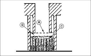
6. Electrolyte (B) should be 6 mm (1/4 in.) above plates (C).
7. Add distilled water, if necessary, to battery cells.
9. Install left side panel, close engine cover, and rear service door.
Charging the Battery
1. Park machine safely. (See Parking Safely in the SAFETY section.)
3. Allow battery to warm to room temperature.
5. Charge battery according the instructions on the battery charger or in the charger operator's manual.
Using Booster Battery


1. Connect positive (+) booster cable to booster battery (A) positive (+) post (C).
2. Connect the other end of positive (+) booster cable to the disabled vehicle battery (B) positive (+) post (D).
3. Connect negative (-) booster cable to booster battery negative (-) post (E).
4. Connect the other end (F) of negative (-) booster cable to a metal part of the disabled machine frame away from battery.
5. Start the engine of the disabled machine and run machine for several minutes.
6. Carefully disconnect the booster cables in the exact reverse order: negative cable first and then the positive cable.
Replacing Fuses
Fuse for Accessories, Seat Switch and Key Switch:

1. Locate fuse panel cover (A) in operator's station on right side.
3. Pull bad fuse out of socket.
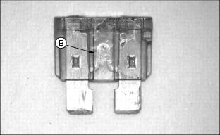
4. Check metal clip (B) in fuse window. Discard fuse if clip is broken.

5. Push new fuse into proper socket. Be sure new fuse is the same amperage as removed fuse.
Fuse for Optional Heater/Defroster:
1. Park machine safely. (See Parking Safely in the SAFETY section.)
2. Raise ROPS and ensure ROPS is safely in the locked position.

3. Locate 15 amp heater/defroster fuse (A), found on the heater/defroster engine wiring harness located over the engine flywheel housing.
5. Check metal clip in fuse window. Discard fuse if clip is broken.
6. Push new 15 amp fuse into socket. Be sure new fuse is the same amperage as removed fuse.
Fuse for Optional Backup Alarm:
1. Park machine safely. (See Parking Safely in the SAFETY section.)

3. Locate 10 amp backup alarm fuse (G), found on the backup alarm wiring harness located between the skid steer fuse block and engine flywheel.
5. Check metal clip in fuse window. Discard fuse if clip is broken.
6. Push new 10 amp fuse into socket. Be sure new fuse is the same amperage as removed fuse.
Replacing Work Light Bulb (Front or Rear)
IMPORTANT: Avoid damage! DO NOT touch new bulb. Oils from skin can shorten bulb life. Install new bulb using cloth or gloves. |
1. Park machine safely. (See Parking Safely in the SAFETY section.)
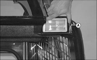
2. Push the light housing (A) on the notched side to compress the spring clip.
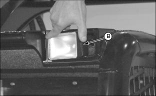
3. Pull the housing (B) out of the ROPS frame. Disconnect wire harness.
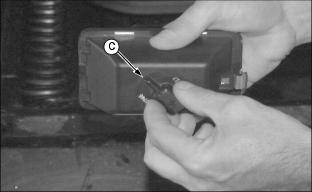
4. Twist the bulb retainer (C) counterclockwise turn. Remove retainer.
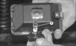
5. Discard old bulb (D), insert new bulb into retainer.
6. Place retainer in housing and turn clockwise turn. Connect wire harness.
7. Place spring clip in ROPS frame housing. Push to compress spring and pivot light housing into frame.