![]()
Introduction
Safety Signs
Controls
Operating
Lawn Care
Replacement Parts
Service Machine Safely
Service Intervals
Service Engine
Changing Engine Oil And Filter
Cleaning Air Intake Screen And Radiator
Checking Air Restriction Indicator
Service Transmission
Service Steering & Brakes
Service Electrical
Service Miscellaneous
Troubleshooting
Storing Vehicle
Assembly
Specifications
Warranty
John Deere Quality Statement
Copyright© Deere & Company

Service Engine
Avoid Fumes
· If it is necessary to run an engine in an enclosed area, use an exhaust pipe extension to remove the fumes. |
Engine Oil
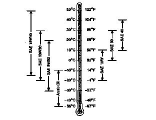
Use oil viscosity based on the expected air temperature range during the period between oil changes.
The following oil is preferred:
· John Deere TORQ-GARD SUPREME PLUS-50®
The following oils are also recommended:
· John Deere TORQ-GARD SUPREME®
Other oils may be used if they meet one of the following:
· API Service Classification CE
· API Service Classification CD
Engine Oil (Continued)
If John Deere TORQ-GARD SUPREME PLUS-50 engine oil and a John Deere oil filter are used, the oil and filter service interval may be extended by 50 hours.
If diesel fuel exceeding 0.5% sulfur content is used, reduce the service interval for engine oil and filter by 50%.
Oils meeting Military Specification MIL-L-46167B may be used as arctic oils.
Checking Engine Oil Level
1. Park Front Mower on a level surface.
2. Check engine oil when oil is cold.
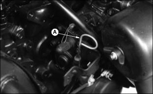
4. Remove dipstick (A). Wipe dipstick with a clean rag.
6. Remove dipstick. Check oil level on dipstick.
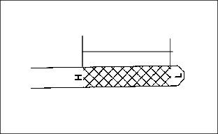
7. Oil must be between FULL mark "H" and LOW mark "L" on dipstick.
8. If oil level is low, remove oil filler cap.
9. Add oil to bring oil level no higher then the "F" mark on dipstick. (See Engine Oil in this section for correct oil.)
11. Install and tighten oil filler cap.
Changing Engine Oil
And Filter
1. Park Front Mower on a level surface.
2. Run engine a few minutes to
warm oil.
6. Remove drain plug. Drain oil in pan.
7. While oil is draining, change oil filter.
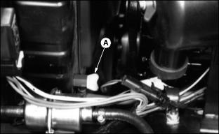
9. Put a drain pan under filter (A).
10. Remove filter using a filter wrench. Turn filter counterclockwise.
11. Apply a film of clean engine oil
on seal of new filter.
12. Install filter. Turn filter until seal contacts mounting surface. Then turn filter BY HAND 1/2 turn more.
13. Install and tighten drain plug.
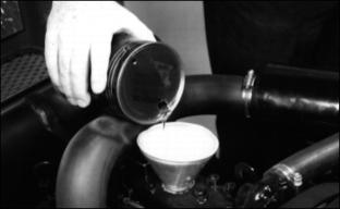
14. Remove filler cap. Add approximately 3.1 L (3.3 qt) of oil. (See Engine Oils in this section for correct oil.)
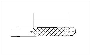
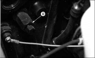
15. Remove dipstick (B) to check
oil level. Add oil only to FULL mark "H" on dipstick.
NOTE: Mark "L" is low oil level
on dipstick.
17. Start engine and run at slow speed for 2 minutes. Check for leaks around filter and drain plug.
18. STOP engine. Check oil level.
19. Install dipstick. Lower hood.
Cleaning Air Intake Screen
And Radiator

2. Loosen three wing nuts to remove screen.
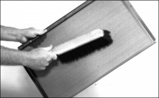
3. Clean screen with a brush or compressed air.
4. Clean air intake screen and radiator cooling fins using compressed air or a brush.
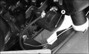
Checking Air Restriction
Indicator
· DO NOT replace primary element unless air restriction indicator (A) shows 635 mm (25 in.) vacuum.
· DO NOT replace secondary element unless air restriction indicator shows 500 mm (20 in.) vacuum after primary element is replaced.
· It is normal for air restriction indicator to show at least 380 mm (15 in.) vacuum after primary element is replaced.
Service Cooling System Safely
Engine Coolant
Use ethylene glycol base coolant. Use coolants only designed for heavy duty diesel engines.
Check container label before using.
IMPORTANT: Avoid damage! To prevent engine damage, DO NOT use pure antifreeze or more than 50% antifreeze in the cooling system. DO NOT mix or add any other type additives to the cooling system. |
Mix approximately 50 percent antifreeze with 50 percent distilled or deionized water. This mixture will provide freeze protection to -37 degrees C (-34 degrees F).
Certain geographical areas may require lower temperature protection. See the label on your antifreeze container or consult your John Deere dealer to obtain the latest information and recommendations.
Engine Coolant (Continued)
The recommended antifreeze provides:
· Corrosion-resistant environment within the cooling system.
· Compatibility with cooling system hose and seal material.
· Protection during cold and hot weather operations.
Checking Coolant Level
· Do not remove radiator cap unless the engine is cool. |
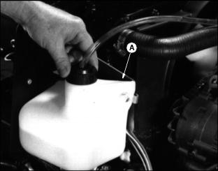
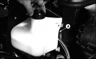
2. Coolant level must be 25-51 mm (1-2 in) in recovery tank (A).
3. If coolant is low, remove coolant recovery tank cap.
4. Add 50 percent ethylene glycol (without stop-leak additive) antifreeze and 50 percent water to proper level.
5. Install and tighten coolant recovery tank cap.
6. Clean debris from air intake screen and radiator. (See Cleaning Air Intake Screen and Radiator in this section.)
7. Check condition of hoses. Check for leaks or loose connections.
Draining Cooling System
· Do not remove radiator cap unless engine is cool. |
1. STOP engine. Let engine cool.
3. Slowly remove radiator cap.
4. Open radiator petcock (A). Drain coolant into a bucket.
5. Loosen block drain (B) one or two turns and drain coolant from engine block.
6. After all coolant has drained, close radiator petcock and tighten block drain.
7. Flush cooling system. (See Flushing Cooling System this section.)
Flushing Cooling System
IMPORTANT: Avoid damage! To prevent engine damage, DO NOT pour water into a hot engine. DO NOT operate engine without coolant. |
1. Fill cooling system with clean water and John Deere Cooling System Cleaner, or John Deere Cooling System Quick Flush or an equivalent. Follow directions on can.
2. Install and tighten radiator cap.
3. Start and run engine until it reaches operating temperature.
4. Drain cooling system immediately before rust and dirt settle.
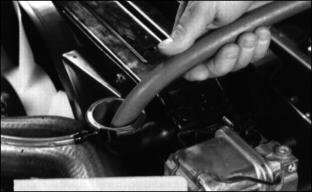
6. Remove and clean recover tank (A).
7. Install tank after cleaning.
8. Fill cooling system. (See Filling Cooling System this section.)
Filling Cooling System
IMPORTANT: Avoid damage! To prevent engine damage, DO NOT use straight antifreeze or more than 50% antifreeze in the cooling system. DO NOT mix or add any other type additives to the cooling system. |
NOTE: F925: Cooling system capacity is 4.7 L (5 qt).
F935: Cooling system capacity is 4.7 L (5 qt).
· Use a solution of only low silicate ethylene glycol antifreeze (without a stop-leak additive) and clean, soft water.
· A chart on the antifreeze container tells how much antifreeze to use for freeze protection needed in your area.
2. When operating engine in extremely cold temperatures:
· See your John Deere dealer for information on arctic operation.
3. For temperatures above freezing:
· Fill cooling system with clean, soft water and John Deere Engine Coolant Conditioner.
4. John Deere Cooling System Sealer or its equivalent may be added to the radiator to seal leaks. Do not use any other additives in the cooling system.
5. Install and tighten radiator cap.
6. Run engine until it reaches operating temperature.
8. After engine cools, check coolant level in recovery tank. Level should be approximately 25-51 mm (1-2 in).
9. Remove cap to add coolant, if necessary.
10. Check condition of coolant system hoses.
11. Install new hoses, if necessary.
12. Tighten hose clamps, if necessary.
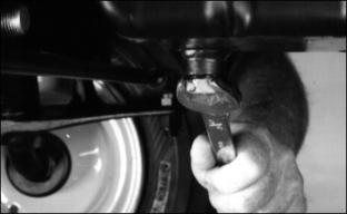
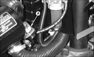
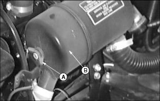
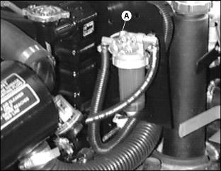
Fuel Filter And Sediment Bowl
Clean the sediment bowl and change the filter.
1. Turn fuel tank pointer to OFF.
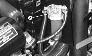
2. Turn collar (A) counterclockwise to remove bowl and filter.
3. Clean bowl. Replace filter.
4. Bleed fuel system. (See Bleeding Fuel System in this section.)
Replacing Primary Element
IMPORTANT: Avoid damage! DO NOT clean primary element.
· DO NOT replace primary element unless air restriction indicator shows |
2. Remove wing nut (A) and cover (B).
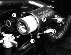
3. Remove and discard wing nut and washer (C).
4. Remove and discard old primary element (D).
5. Wipe dirt from inside of cannister with a soft cloth.
6. Install new primary element.
7. Install new wing nut and
washer.
9. Install old cover with washer and wing nut.
11. Depress reset button (E) on air restriction indicator (F) and then release to reset.
12. Start engine and allow it to run a minute at maximum speed.
13. STOP engine and check air restriction indicator. If indicator shows 500 mm (20 in) or more vacuum, replace secondary element.
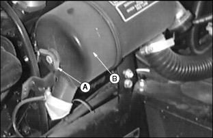
Replacing Secondary Element
1. Remove primary element. (See Replacing Primary Element in this section.)
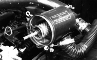
2. Remove wing nut (A) and secondary element (B).
3. Install new secondary element.
4. Install washer and wing nut.
IMPORTANT: Avoid damage! It is normal for air restriction indicator to show at least 380 mm (15 in) vacuum, after primary element is replaced. |
6. Install new primary element.
(See Replacing Primary Element this section.)
7. Install washer and wing nut.
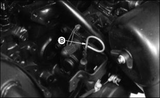
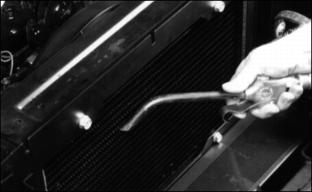
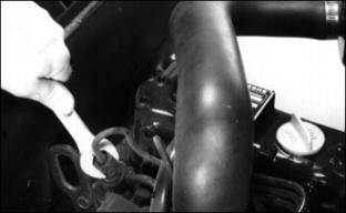
Bleeding Fuel System
NOTE: When mower is run out of fuel, the air in the fuel system must be removed. Late model mowers are self bleeding, and will restart after a short period of cranking engine.
1. Fill fuel tank. Turn fuel supply lever towards side with full tank.
2. Loosen bleeder screw (A) a few turns to open air vent.
3. Turn key switch to run position to run fuel pump until fuel appears at bleeder screw, then turn key switch to off position.
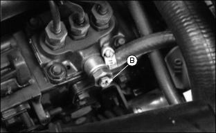
5. Loosen bleeder screw (B) at fuel injection pump.
6. Turn key switch to run position to run fuel pump.
7. Run fuel pump until fuel appears
at bleeder screw, then turn key switch to off position.
9. Using a 17 mm wrench, loosen nuts on all three high pressure fuel lines while holding a backup wrench on the injector body.
10. Use starter to turn engine over.
11. When fuel appears at injectors, tighten injector nuts.
12. Start engine. If engine does not start, repeat bleed procedure.
Lubricating Engine Driveshaft
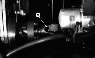
Lubricate U-Joint fitting (A) with
one or two shots of John Deere Multipurpose Grease or equivalent.
Replace/Adjust Fan Belt
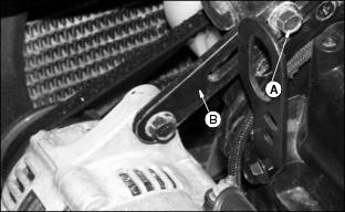
2. Loosen fan belt by sliding alternator bracket (B) torwards engine.
3. Pull fan belt from alternator pulley.
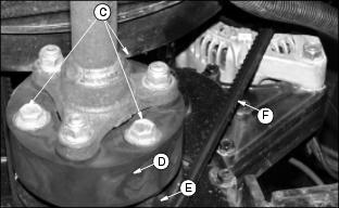
4. Remove three cap screws (C) holding vibration dampener (D) to engine pulley (E).
5. Remove fan belt from engine pulley and pull up between vibration dampener and engine pulley.
6. Pull fan belt forward off of fan blades and remove from mower.
7. Installation is in the reverse of removal. First route fan belt over fan, then over engine pulley, then over alternator pulley.
8. Install vibration dampener cap screws and torque to specs.
9. Adjust fan belt tension. Belt should deflect 6 mm (1/4 in.) with light-to-moderate pressure at (F).