![]()
Introduction
Safety Signs
Controls
Operating
Replacement Parts
Service Machine Safely
Service Interval Chart
Service Battery
Service Electrical
Service Miscellaneous
Troubleshooting
Storing Machine
Assembly
Remove Protective Plastic From Hood and Front Fenders
Using the Service/Drive Switch
Specifications
Warranty
John Deere Service Literature
QUALITY DOESN'T END WHEN YOU INVEST IN A DEERE
Copyright© Deere & Company

Assembly
Prepare for Assembly
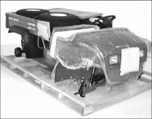
1. Remove utility vehicle from shipping crate.
2. Raise vehicle using a safe lifting device. Position safety stands under vehicle.
3. Locate and identify all assembly parts and hardware.
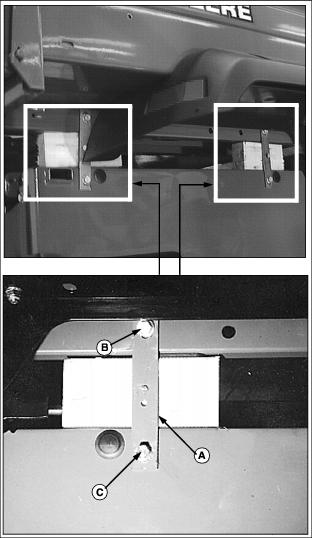
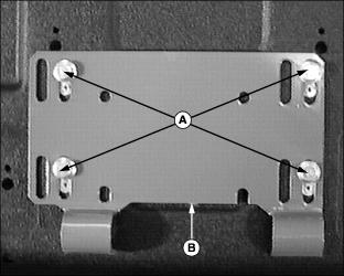
4. The steel cargo box is attached on each side of the frame with two shipping straps (A).
NOTE: Thread forming screws (B) must be retained for installation of vehicle load guard.
Thread forming screws (B) attaching the rear shipping strap to the cargo box on each side of the vehicle may be difficult to remove. It may be necessary to loosen the hardware attaching the rear of each cargo box fender to the bottom of the cargo box.
5. Remove thread forming screws (B).
· Retain thread forming screws (B) removed from each of the four shipping straps.
6. Use a safe lifting device to lift the steel cargo box off of the vehicle frame.
· Remove thread forming screws (C) and shipping straps (A).
7. Install both thread forming screws (C) back into holes they were removed from on RIGHT side of vehicle. Install thread forming screw (C) back into the rear hole only on the LEFT side of the vehicle.
· Discard shipping straps and one thread forming screw removed from the front LEFT side of utility vehicle.
Checking Tire Pressure
2. Check tire pressure with an accurate gauge.
Install Wheels and Tires
Check Tire Inflation Pressures
· Keep all tires inflated to 69 kPa (10 psi).
· Mount wheels with valve stem to the outside.
Installing Rear Wheels
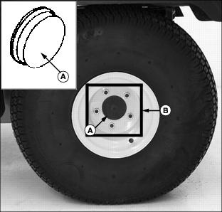
1. Install plastic cap (A) inside each rear wheel axle shaft hole.
2. Attach one wheel to each rear axle using five wheel nuts (B), tighten until snug.
· Tighten rear wheel nuts alternately to 88 N·m
(65 lb-ft.).
Installing Front Wheels
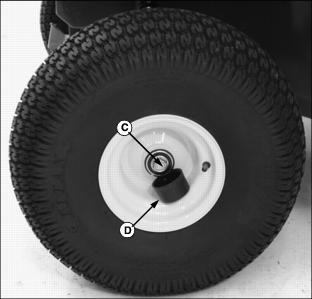
1. Attach one wheel to each side of vehicle using a
M16 x 40 flanged cap screw (C).
· Tighten cap screws to 90 N·m (66 lb-ft.).
Install Steering Wheel
Coat steering shaft with multi-purpose grease.
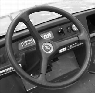
3. With front wheels straight and facing forward, install steering wheel.
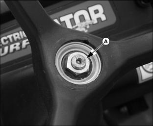
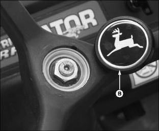
4. Install hex nut (A) and tighten.
Lubricating Front King Pins
NOTE: In extreme conditions lubrication should be done more frequently.
1. Park vehicle on hard, level surface.
2. Turn the key switch to the OFF "0" position.
3. Move the directional control lever to the NEUTRAL (N) position.
5. Raise front of utility vehicle with a safe lifting device.
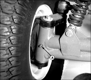
6. Lubricate one grease fitting (A) on each king pin axle arm with the preferred grease or an equivalent. (See Grease in the Service-Miscellaneous section.)
Install Operator Seat
1. Remove hardware (A) from bottom of seat base bracket (B).
2. Position rubber seat bushings (C) onto seat frame rail with tabs facing to the rear.

3. Position seat base bracket (B) onto rubber seat bushings (C).
NOTE: There is only one correct position laterally for each seat. Use inboard slots shown when installing the seats.
Both vehicle seats are adjustable. See Adjusting Seats in the Operating section for seat adjustment procedure.
4. Rotate seat base bracket (B) into an upward position and attach seat with hardware (A).
Install Load Guard
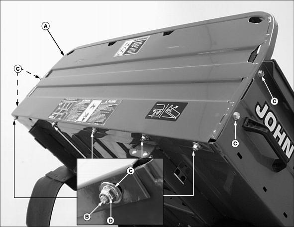
1. Position load guard (A) onto the cargo box as shown.
· Bottom lip of load guard should be installed to the underside of the cargo box.
· Square tubular frame surrounding the perimeter of the load guard should be attached inside the cargo box.
2. Attach bottom of load guard using M8 x 20 carriage head bolts (B), flat washers (C) and flanged lock nuts (D).
· Tighten hardware to 25 N·m (18 lb-ft.).
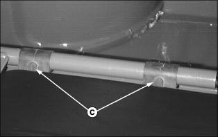
3. Attach sides of load guard using thread forming screws (C).
NOTE: Screws (C) were retained when shipping straps were removed from the cargo box.
Install Cargo Box
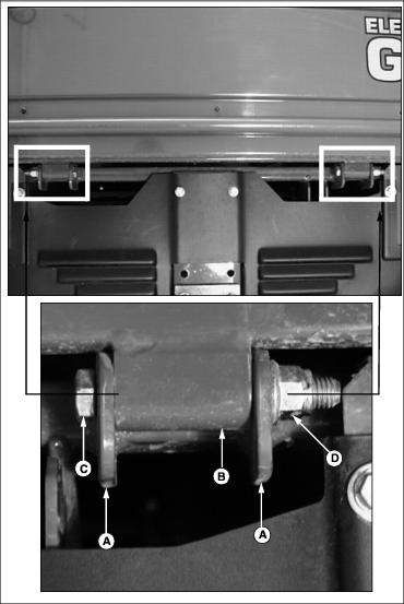
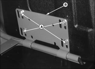
1. Install cargo box onto the vehicle frame. Align frame tabs (A) and cargo box bushings (B).
NOTE: Install cap screws with threads facing to the outside of the vehicle.
2. Attach box at rear on each side using M12 x 90 cap screws (C) and flanged lock nuts (D).
NOTE: If it is necessary to tighten cap screws to squeeze tabs to minimize noise from vibration. Spray lube is used to eliminate squeaks until pivot points wear in.
3. Tighten cap screws pulling in tabs until they contact ends of bushings.
4. Spray bushings and tab area with a spray lubricant.
Install Cargo Box Support Rod
Cut tie strap and release support rod from stored position on cargo box frame.

· The 90° bent end of rod (A) is installed in cargo box frame.
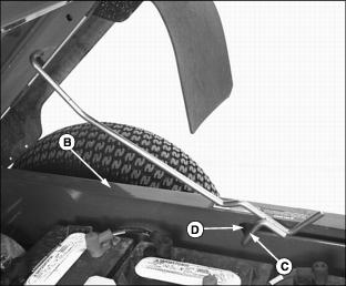
5. Push inward on support rod forcing it over sill (B).
6. Route end of support rod (C) into slot (D).
7. Lift up on cargo box and latch rod into notch in slot.
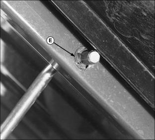
Adjust Cargo Box Latch
The cargo box latch is installed in the lowest position when shipped from the factory. For complete instructions on how to adjust the latch, see Adjust Cargo Box Latch in the Service-Miscellaneous section.
Remove Protective Plastic From Hood and Front Fenders
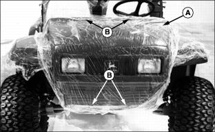
· Loosen and remove four screws (B).
· Carefully lift hood up and off vehicle.
3. Using a sharp utility knife, carefully slit protective plastic where fenders join metal frame.
4. Pull plastic up and away from fenders. Remove remaining plastic in joint by pulling from below.
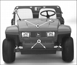
5. Install hood (A) onto vehicle.
· Install and tighten top two screws (B).
· Push hood upward. Allow equal clearance around each headlight housing.
· Install and tighten two bottom screws (B).
6. Clean plastic and painted surfaces. (See Cleaning and Polishing Plastic Hood and Fenders in the Service-Miscellaneous section.)
Charge the Batteries
For complete instructions on how to operate the battery charger provided with this utility vehicle, review the instructions supplied with the charger and see Using the Battery Charger in the Operating section.
Using the Service/Drive Switch
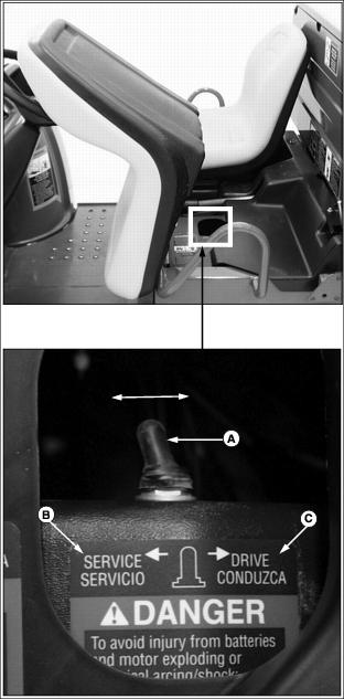
NOTE: This utility vehicle is packaged and shipped from the factory with the service/drive switch in the SERVICE position.
This utility vehicle is equipped with a two position service/drive toggle switch.
· Raise and tilt operator seat forward to locate switch.
Service Position
When the vehicle service/drive switch (A) is moved to the SERVICE position (B) the vehicle is disabled and prohibited from being driven.
The service/drive switch should be moved to the SERVICE position when:
· Performing any service function on the vehicle.
· The vehicle is not going to be in service for an extended period of time (one month or more).
Drive Position
When the vehicle service/drive switch (A) is moved to the DRIVE position (C) the vehicle controller is energized. When the key switch is turned to the ON "1" position, controls are energized and the vehicle is ready for normal operation.