![]()
Introduction
Safety Signs
Controls
Operating
Replacement Parts
Service Machine Safely
Service Interval Chart
Service Battery
Battery Position and Connection Diagram
Tighten Battery Terminal Connections
Cleaning or Replacing Batteries
Checking Battery Electrolyte Levels
Service Electrical
Service Miscellaneous
Troubleshooting
Storing Machine
Assembly
Specifications
Warranty
John Deere Service Literature
QUALITY DOESN'T END WHEN YOU INVEST IN A DEERE
Copyright© Deere & Company

Service Battery
Battery Safety
Using Deep Cycle Batteries
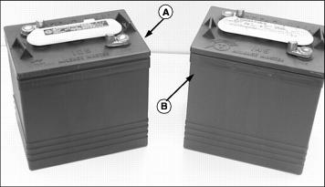
A - Standard Battery Type (Trojan T105)
B - Optional Battery Type (Trojan T145)
A cycling battery has a service requirement which is quite different than that of an automotive battery.
The automotive battery must deliver high cranking currents at a satisfactory voltage for a few seconds and a portion of the accessory load (10-25 amperes) for a minute or two at a time in city or heavy traffic. Therefore, the automotive battery is designed with maximum plate area and low internal resistance to provide high cranking performance. Power taken from this battery is immediately replaced by the alternator or generator. Therefore, the battery is subjected to shallow discharge cycles (2-3% of the battery capacity). These batteries operate in the 90-100% state of charge.
Cycling batteries supply all the motive power and power for the accessories for the vehicles in which they are used. The rate of discharge varies with the type of service. In electric vehicle service, the battery normally provides a nominal intermittent discharge of 75 amperes, with a typical range of 40-350 amperes. The depth of discharge varies with the length of time it is used before being recharged. Once the battery is discharged, it must be recharged to continue operating the vehicle. The batteries used in this utility vehicle usually receive "deep" discharge (60% or more of their capacity).
NOTE: New cycling batteries do not have their full capacity until they have been cycled several times (usually between 20 and 50 cycles). Therefore, they can be excessively discharged early in their vehicular life, thereby shortening their service life.
Cycling batteries are designed to have good life performance in "deep" cycle service. The major cause of battery failure in "deep" cycle service is poor maintenance:
· Dirt or corrosion on battery tops or terminals.
· Water too much or too little.
· Excessive discharge (lack of charging).
A battery is a perishable item that requires periodic maintenance. With a reasonable amount of care, the life of a battery can be significantly extended.
The life of a cycling battery is determined not only by the number of cycles (a discharge and recharge) it receives, but also by the depth of each cycle. Assume a set of batteries is used four hours per day; lets call that one cycle. If they are used for eight hours, this is a much deeper discharge and is equivalent to approximately three cycles. A battery set used eight hours per day has a life span approximately one-third that of one used for four hours per day.
Electrolyte and Specific Gravity
The electrolyte in a lead-acid storage battery is a dilute sulfuric acid solution. A battery with a fully charged specific gravity of 1.250 corrected to 26.7°C (80°F) contains an electrolyte with approximately 33.9% sulfuric acid by weight or 23.5% by volume. The remainder of the electrolyte is water. Pure (concentrated) sulfuric acid has a specific gravity of 1.835.
The sulfuric acid in the electrolyte is one of the necessary ingredients for the chemical reactions taking place inside the battery. It supplies the sulfate ions (SO4) which combine with the active material in the plates. It is also the carrier for the electric current as it passes from plate to plate. When the battery terminals are connected to an external load, the sulfate combines with the active materials of the positive and negative plates forming lead sulfate (PbSO4) on both and releasing electrical energy.
Specific gravity is a unit of measurement for determining the sulfuric acid content of the electrolyte. The recommended fully charged specific gravity of most batteries today is in the range of 1.250-1.280 corrected to 26.7°C (80°F). The information in this manual will assume a fully charged specific gravity of 1.250 or higher.
On the specific gravity scale, water by definition is 1.000. Therefore, electrolyte with a specific gravity of 1.250 means it is 1.250 times heavier per unit volume than pure water.
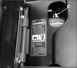
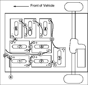
Battery Position and Connection Diagram
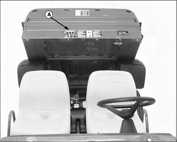
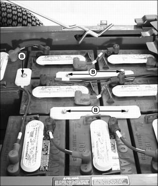
· A battery position and connection safety/diagram label (A) is attached to the front of the vehicle cargo box. Always refer to the battery position/connection diagram:
· Before and during battery installation.
· When making electrical connections.
· Always replace batteries in the same numbered position and orientation as shown in the battery/position connection diagram.
NOTE: Battery cables that are of the same length and labeled the same can be interchanged.
· Always replace battery cables in the same position and orientation as shown in the battery/position connection diagram. Battery cables are of specific length for each connection. Battery cables are labeled to assist with proper installation when removed.

· Battery cables labeled "A" (4 cables)
· Battery pack POSITIVE cable labeled "B+" (1 cable and 1 wire)
· Battery pack NEGATIVE cable labeled "B-" (1 cable and 2 wires)
· Battery cables labeled "C" (2 cables)
· Battery cable labeled "D" (1 cable)
· Battery connections are marked:
· Always verify that the RED boots covering the battery terminal and wire terminal are on the battery POSITIVE (+) terminal.
· Always verify that the BLACK boots covering the battery terminal and wire terminal are on the battery NEGATIVE (-) terminal.
Checking Batteries
A visual inspection of vehicle batteries is intended to find and correct potential problems before they create more serious safety and operational concerns. A battery is a perishable item that requires periodic maintenance. With a reasonable amount of care, the life of a battery can be significantly extended.
On a daily basis and before the vehicle is placed on charge a visual inspection should be made of the batteries.
1. Park vehicle on a hard, level surface.
2. Turn key switch to the OFF "0" position.
3. Move the directional control lever to the NEUTRAL "N" position.

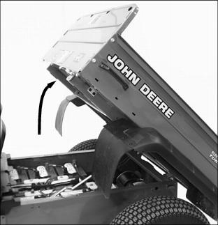
5. Lift and secure cargo box in the raised position.
IMPORTANT: Avoid damage! Discolored or melted terminal boots, burn spots or damage to battery case or terminals are possible signs that the terminal connections may be loose. |
6. Visually inspect all batteries for:

· Discolored or melted terminal boots.
· Dirt or corrosion on or around the battery terminals.
· Damage to battery case or terminals.
7. Tighten battery terminal connections if a problem is detected.
8. Tighten battery hold downs if they are determined to be loose.
9. Clean battery compartment, terminal connections, cable ends and battery(s) if necessary.
10. If necessary, replace any damaged battery(s) and place in an acid resistant container until the battery can be properly disposed of.
11. Check battery electrolyte levels if necessary.
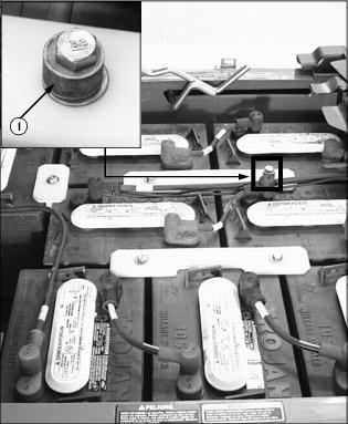
Tighten Battery Terminal Connections
1. Park vehicle on a hard, level surface.
2. Turn key switch to the OFF "0" position.
3. Move the directional control lever to the NEUTRAL "N" position.
NOTE: Turn off all vehicle electric accessories.
5. Raise and tilt operator seat forward.
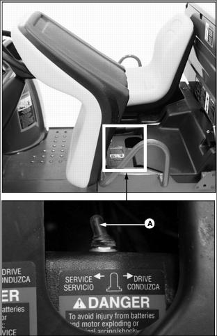
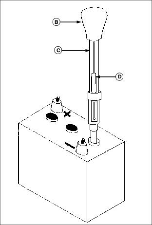
· Move the service/drive switch (A) to the SERVICE position.
6. Lift and secure cargo box in the raised position.
7. Clean battery compartment, terminal connections, cable ends and battery(s) if necessary.
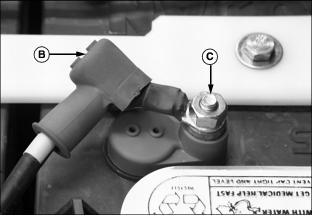
8. Pull the boots (B) on the terminal cables back far enough to expose each terminal connection.
9. Use insulated tools to tighten each terminal connection hex nut (C) to 14-16 N·m (124-142 lb-in.).
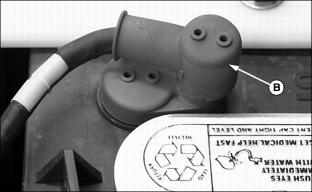
10. Install the proper terminal boots (B) (red on positive and black on negative) securely over each battery terminal.
12. Move the service/drive switch to the DRIVE position.
Tighten Battery Hold Downs
1. Park vehicle on a hard, level surface.
2. Turn key switch to the OFF "0" position.
3. Move the directional control lever to the NEUTRAL "N" position.
5. Raise and tilt operator seat forward.
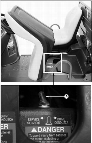
· Move the service/drive switch (A) to the SERVICE position.
6. Lift and secure cargo box in the raised position.
7. Use insulated tools to tighten each battery hold down bolt (B) to 7-9 N·m (62-80 lb-in.).
9. Move service/drive switch to the DRIVE position.
Cleaning or Replacing Batteries
Cleaning Batteries
Cleaning is a key element in battery maintenance, for both safety and performance. Regular cleaning will reduce dirt and corrosion from forming. This reduces the chance of acid contact, and will provide efficient electrical connections. Lack of cleaning can cause the following problems:
· Reduced reliability and performance.
· Shortened overall battery life.
1. Park vehicle on a hard, level surface.
2. Turn key switch to the OFF "0" position.
3. Move the directional control lever to the NEUTRAL "N" position.
NOTE: Turn off all vehicle electric accessories.
5. Raise and tilt operator seat forward.
· Move the service/drive switch (A) to the SERVICE position.
6. Lift and secure cargo box in the raised position.
7. Wash down batteries, battery terminals and battery compartment. If battery corrosion is excessive, additional cleaning of the battery(s) and surrounding area may be necessary.

8. Note the position of each battery in the battery compartment and the location of both the positive and negative terminals.
9. Using insulated tools, remove battery pack POSITIVE (+) cable (B) labeled "B+" and wire from positive terminal on battery labeled number "1" in the diagram.
10. Clean all moisture and corrosion in battery compartment with a solution of one part baking soda to five parts water. Rinse with clean water and allow to dry.
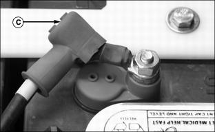
11. Pull the boots (C) on the terminal cables back far enough to expose each terminal for cleaning.
NOTE: Battery positive "+" and negative
"-" connections are marked and color coded.
Battery cables are of specific length and labeled for each connection. See Battery Position and Connection Diagram in this section or refer to the safety/diagram label attached to the front of the vehicle cargo box the for proper installation.
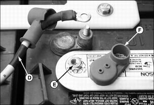
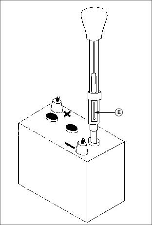
12. Remove cables (D) from battery terminals that are corroded.
Loosen and remove hex nut (E).
· Remove rubber post cover (F).
13. Remove corrosion from battery terminals and cable ends.
· Clean battery terminals and cable ends with a solution of one part baking soda to five parts water. Use a wire brush if additional cleaning is required.
· Rinse all parts with clean water and allow to dry.
Replacing Batteries
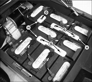
· Remove battery hold down bolts (G).
· Remove battery hold down(s) (H).
· Carefully lift the battery out of the vehicle. Store the battery until it can be properly disposed of.
· Clean plastic battery tray and battery hold downs if corroded or rusty.
· If necessary, remove battery tray and check vehicle supports for corrosion.
· Clean area with a solution of one part baking soda to five parts water.
· Rinse area with clean water and allow to dry.
2. Paint areas affected by rust or corrosion with acid resistant paint.
3. Install batteries in the same position and orientation as shown in the Battery Position/Connection diagram. (See Position and Connection Diagram in this section or diagram attached to the front of the cargo box.)
4. Install battery cables using the Battery Position/Connection diagram as reference.
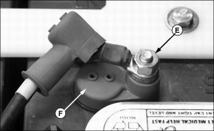
· Install rubber post cover (F).
· Tighten each terminal connection hex nut (E) to 14-16 N·m (124-142 lb-in.).
5. Replace the proper terminal boots (C) (red on positive, and black on negative) securely over each battery terminal.
NOTE: Spacer (I) must be installed under the head of the front left battery hold down bolt with standard T105 batteries only. Use of the spacer will allow the battery to be properly installed and the hold down bolt to be accurately torqued.
6. Install battery hold down (s).
· Torque hold down bolts to 7-9 N·m (62-80 lb-in.).
7. Check the electrolyte level in each battery cell.
Checking Battery Electrolyte Levels
Checking and maintaining electrolyte levels is important to the care and life of the batteries. Improper care of the batteries can lead to premature battery failure due to cell dilution and imbalance.
Electrolyte levels drop during discharge and rise during charging. Therefore, it is essential that the electrolyte levels be checked:
· After each week the vehicle is used.
· At the recommended service interval if the vehicle is in storage. (Refer to the Service Interval Chart section.)
NOTE: To maintain specific gravity balance, battery fluid levels should be the same in all 24 battery cells.
Battery Electrolyte Guidelines
NOTE: Overfilling or underfilling the batteries will void vehicle and battery warranties.
· It is recommended that distilled water be used for filling battery cells. If distilled water is unavailable, any water safe for drinking (except mineral water) can be used. Water that is not distilled should be analyzed. Make sure that the mineral contents of the water used are below those listed in the following table.
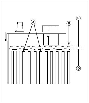
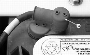
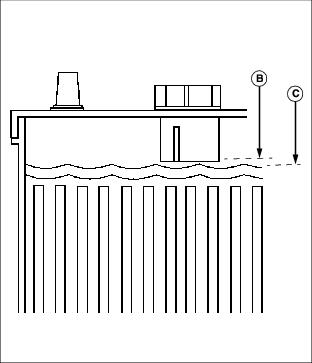
· If the electrolyte level is low, add water near the end of the charge cycle or after taking the battery off charge. Never allow the electrolyte level to drop below the tops of the plates (A) because the exposed portion of the plates will become permanently inactive due to sulfation.
· Never overfill a battery cell above the battery cap level indicator (B).
· MAXIMUM electrolyte fill level (C) is 3 mm
(0.125 in.) below the level indicator.
· MINIMUM electrolyte fill level (D) is 3 mm
(0.125 in.) above plates.
Overfilling the batteries will result in electrolyte loss through the vent caps. This provides a path for self discharge of the battery and also causes corrosion problems.
· Batteries will need to be watered more often:
· Note any large differences in the amount of water needed from cell to cell. All battery cells should gas approximately the same amount, large differences may indicate a defective cell.
Automatic Watering Devices
NOTE: The automatic battery filler must be ordered separately from your John Deere dealer.
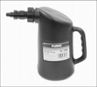
An automatic battery filler container can be used to maintain the correct electrolyte level within the battery cells. This 1.9 L (2 qt) professional battery filler shuts off automatically when battery cells are properly filled.
Checking Electrolyte Level-Before Charging
1. Park utility vehicle on a hard, level surface.
2. Turn key switch to the OFF "0" position.
3. Move directional control lever to the NEUTRAL "N" position.
5. Lift and secure cargo box in the raised position.
6. Check battery electrolyte level.
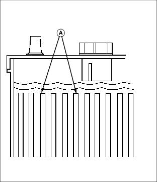
· Carefully remove the battery cap. Look into each cell to see if the electrolyte level is above the top of the plates.
IMPORTANT: Avoid damage! Overfilling a discharged battery with water can easily result in an overflow of electrolyte from the battery cells. |
· If the electrolyte level is below the top of the plates (A), add only enough water to cover the plates before charging.
· If the electrolyte level covers the plates, DO NOT add any water.
8. Repeat battery electrolyte level check for each vehicle battery.
9. Place the vehicle on charge using the charger provided with the vehicle.
Check Electrolyte Level-After Charging
1. Disconnect battery charger. (See Using the Battery Charger in the Operating section.)
2. Turn key switch to the OFF "0" position.
3. Move directional control lever to the NEUTRAL "N" position.
5. Lift and secure cargo box in the raised position.
6. Check battery electrolyte level.
· Carefully remove individual battery caps. Look into each cell to check the electrolyte level.
· Electrolyte level should be 3 mm (0.125 in.) below the battery cap level indicator (B).
IMPORTANT: Avoid damage! Overfilling a discharged battery with water can easily result in an overflow of electrolyte from the battery cells. |
· If the electrolyte level is low, add only enough water to bring the electrolyte to the MAXIMUM level (C).
· If the electrolyte level is at the MAXIMUM level, DO NOT add any water.
8. Repeat battery electrolyte level check for each vehicle battery.
Checking Battery Condition
If the vehicle is not performing satisfactorily, and it is suspected to be battery related, test the battery set and determine battery condition.
An effective way to identify the cause of a poorly performing battery is to perform a hydrometer test. Using a hydrometer will identify a battery in a set with a lower than normal specific gravity. Once the particular cell or cells that are the problem are identified, the suspect battery can be removed and replaced.
Hydrometer
NOTE: The hydrometer must be ordered separately from your John Deere dealer.
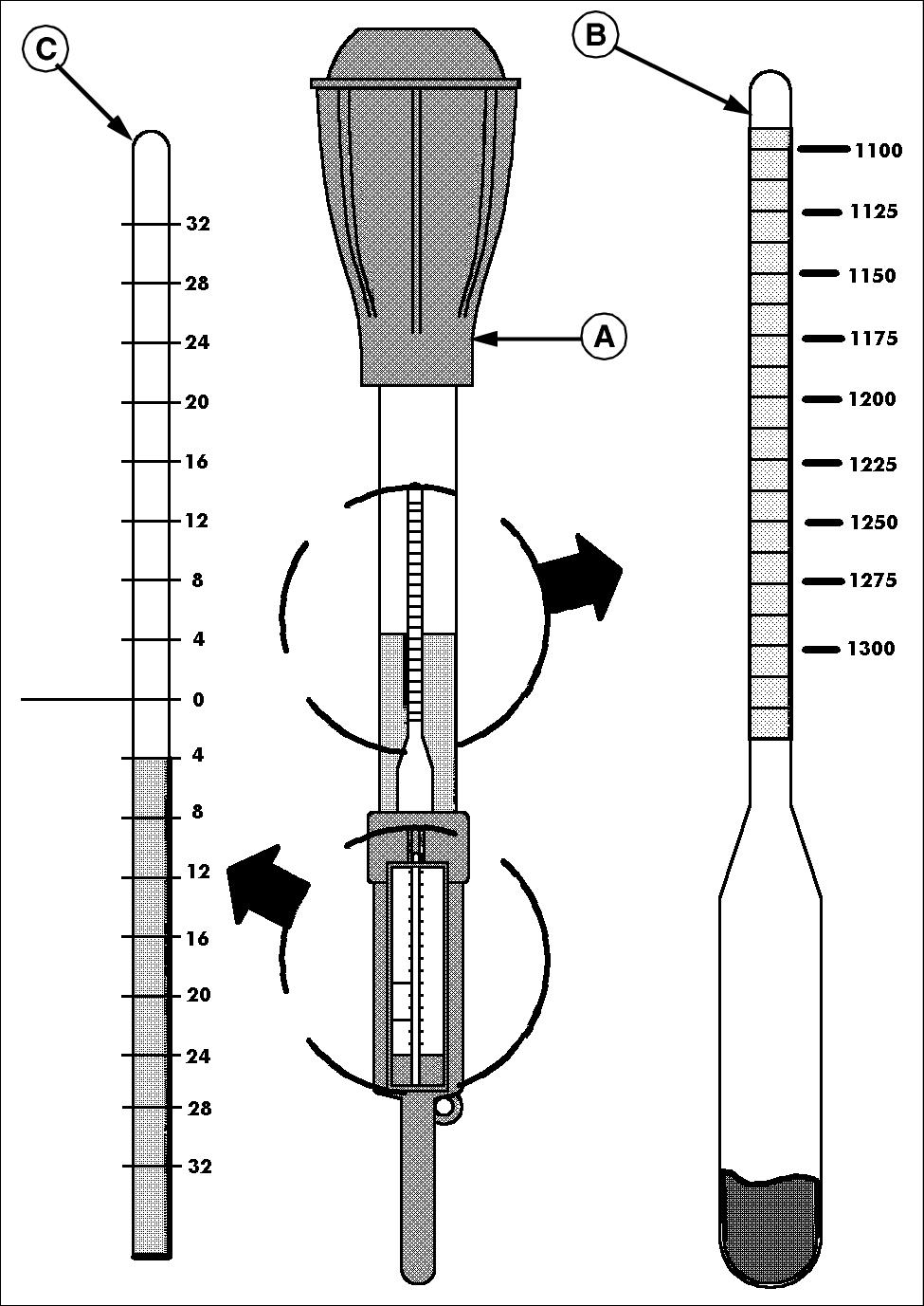
· The state-of-charge of a lead acid battery can be determined by the specific gravity of the electrolyte (its weight compared to water). The specific gravity can be measured directly with a hydrometer (A).
· A hydrometer is a bulb-type syringe which will extract electrolyte from a battery cell. A glass float (B) in the hydrometer barrel is calibrated to read in terms of specific gravity.
· The range of specific gravity used on these floats is 1.140 to 1.325.
· DO NOT assume a battery will not take a charge because you have been charging it for a while and the float will not rise. The battery may have been fully discharged and will require considerable charging before reaching the minimum specific gravity on the float.
· The lower the float sinks in the electrolyte, the lower its specific gravity.
· Hydrometer floats are calibrated to give a true reading at one fixed temperature only. The hydrometer is equipped with an internal thermometer (C) that will measure the temperature of the electrolyte and will include a conversion scale to correct the float reading.
· A correction factor must be applied for any specific gravity reading made when the electrolyte temperature is not 26.7°C (80°F). A temperature correction must be used because the electrolyte will expand and become less dense when heated. The float will sink lower in the less dense solution and give a lower specific gravity reading. The opposite occurs if the electrolyte is cooled. It will shrink in volume, becoming more dense. The float will rise higher and give a false high reading.
· A correction factor of 0.004 specific gravity (sometimes referred to as 4 "points of gravity") is used for each 5.5° (10°F) change in temperature. Four "points of gravity" (0.004) are added to the indicated reading each 5.5°C (10°F) increment above 26.7°C (80°F) and four points are subtracted for each 5.5°C (10°F) below. This correction is important at temperature extremes because it can be a substantial value.
· Example 1: A partially discharged battery is installed in this vehicle at 6.7°C (20°F). A hydrometer reading of 1.250 would indicate that the battery is almost fully charged. However, when the correction factor is applied, the true value is 1.226 only 75% charged.
· Example 2: A battery exposed to the sun in hot weather can easily exceed 43°C (110°F). A hydrometer reading of 1.238 might indicate a low state of charge, or there is a problem with the electrical system if the battery is already in service. However, when the correction factor is applied, the true value is 1.250, 100% charged.
Using a Hydrometer
1. Park vehicle on a hard, level surface.
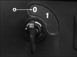
2. Turn key switch to the OFF "0" position (A).
3. Move directional control lever to the NEUTRAL "N" position.
5. Move the service/drive switch to the SERVICE position.
7. Inspect battery terminals, boots and case for breakage, cracks, hot spots or discoloration. Repair as needed.
8. Refer to the battery test log and prepare to record pertinent hydrometer test information. (See Battery Test Log in this section.)
IMPORTANT: Avoid damage! Help prevent contaminants from entering individual battery cells. Clean all dirt and moisture from battery tops before removing battery caps. |
9. Carefully remove the battery cap from the battery to be tested.
NOTE: DO NOT perform a hydrometer test on a battery that has just been watered. The battery will be required to go through at least one charge and discharge cycle to mix the electrolyte and ensure a reliable measurement.
The barrel must be held vertically so the float is not rubbing against the side of the barrel.
10. Squeeze the bulb (B) of the hydrometer. Insert the tip into the battery cell and allow the bulb to expand drawing electrolyte into the barrel (C).
· The float (D) must lift freely, touching neither the side, top or bottom stopper of the barrel.
NOTE: The thermometer used should be of the mercury-in-glass type with a scale reading as high as 52°C (125°F).
Do not insert a metal thermometer into a battery. Use a hydrometer with a built in thermometer that is designed for testing batteries.
· The electrolyte should be drawn in and out of the hydrometer barrel several times to permit the thermometer (E) to adjust to the temperature of the electrolyte in the cell.
NOTE: Disregard the curvature of the liquid where the surface rises against the float stem and the barrel due to surface tension.
· Hold the hydrometer in a vertical position at eye level. Read and note the specific gravity level of each cell by looking across the surface of the electrolyte to the float. The float is calibrated with a scale that ranges from 1.140 to 1.325.
· The following chart illustrates the approximate state of charge based on the specific gravity reading for the battery pack.
NOTE: If the battery cells have been overfilled frequently due to inappropriate amounts of water being added, there will be a gradual drop in specific gravity.
11. Correct the reading for temperature.
· Four "points of gravity" (0.004) are added to the indicated reading each 5.5°C (10°F) increment above 26.7°C (80°F) and four points are subtracted for each 5.5°C (10°F) below 26.7°C (80°F). Adjust the reading to conform with the electrolyte temperature.
12. Repeat this procedure for each cell of each battery.
· If the variation between the highest and lowest cell readings in any one battery is 0.030 (30 gravity points) or more, it probably has a failing cell.
13. Identify the battery(s) and the cell(s) that vary by more than 0.030 points and perform a battery discharge test. (Refer to vehicle technical manual for the Battery Discharge Test procedure.)
Battery Test Log
The battery test log should be used whenever a battery set is tested and a problem is suspected. Because battery testing is based on both specific data and comparison data the form will help identify specific batteries with a problem.
The form is designed to group the test result to give a quick and accurate diagnosis of a battery problem. By looking across the rows, comparisons between one battery and the rest of the set can be made. By looking down the columns individual battery patterns can be identified. If a battery set or battery consistently give good results, the battery set is good and any problem that may have initiated the testing is in some other vehicle operating system. If a battery set or battery in a set consistently provides poor results, the battery set or battery within the set is bad and should be replaced.
The following formula statements can be used to assist in determining the proper temperature correction to be added or subtracted to the uncorrected hydrometer readings. Formula statement 1 is to be used if the temperature of the electrolyte is above 26.7°C (80°F). Formula statement 2 is to be used if the temperature of the electrolyte is below 26.7°C (80°F).
Formula Statement 1 is ____-80=____/10=____x .004=____ Add this number to your hydrometer readings.
Formula Statement 2 is 80-____=____/10=____x .004=____ Subtract this number from your hydrometer readings.