![]()
Introduction
Safety
Controls
Operating
Replacement Parts
Service Machine Safely
Service Interval Chart
Service Engine
Service Transmission
Service Steering and Brakes
Remove and Install Front Wheels
Remove and Install Rear Steering Wheel
Lubricating Rear Steering Wheel Bearing and Spindle
Lubricate Neutral Detent Plate Slots
Checking and Aligning Control Levers
Service Electrical
Service Miscellaneous
Troubleshooting
Storage
Assembly
Specifications
Warranty
John Deere Service Literature
John Deere Quality Statement
Copyright© Deere & Company

Service Steering and Brakes
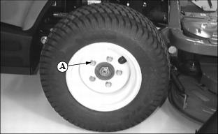
Remove and Install Front Wheels
Removing:
1. Park front mower on a level surface.
2. Stop engine and engage park brake.
3. Slightly loosen five wheel bolts (A).
4. To remove the front wheel on the RIGHT side of the Front Mower:
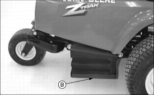
· Lift mower with jack in position (B). Make sure jack is centered under portion of engine base supporting the fuel tank.
5. To remove the front wheel on the LEFT side of the Front Mower:
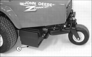
· Lift mower with jack in position (C). Make sure jack is centered under portion of engine base supporting the battery.
Installing:
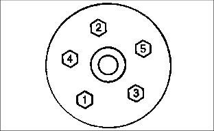
· Tighten wheel bolts in numbered sequence shown for safe wheel installation. Tighten alternately until recommended torque value is reached.
· Tighten bolts to 100 N·m (75 lb-ft.).
Remove and Install Rear Steering Wheel
Removing
1. Stop engine and engage park brake. Rear steering wheel(s) should be pointing straight ahead.
2. Park mower on a level surface.
3. Lift rear of front mower with a safe lifting device.
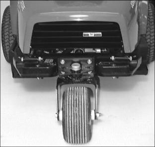
Picture Note: Photo shows front mower equipped with the single rear steering wheel option.
4. Remove hex nut (A) and wheel bolt (B).
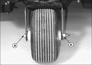
5. Remove wheel from assembly yoke.
Installing
2. Install steel spacer, wheel bolt and hex nut.
Grease
Use grease based on the expected air temperature range during the service interval.
The following greases are preferred:
· John Deere Moly High Temperature EP Grease.
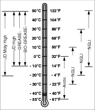
· John Deere High Temperature EP Grease.
Other greases may be used are:
· SAE Multipurpose EP Grease with 3 to 5 percent molybdenum disulfide.
· Greases meeting Military Specification MIL-G-10924C may be used as arctic grease.
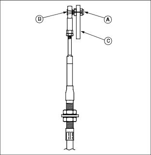
Lubricating Rear Steering Wheel Bearing and Spindle
Lubricate steering wheel bearing(s) (A) and spindle(s) (B). (See Grease in this section for the proper application.)
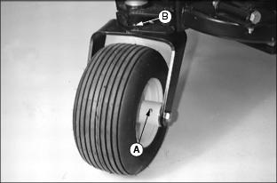
Picture Note: Top photo shows front mower equipped with single rear steering wheel option.
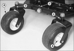
Picture Note: Bottom photo shows front mower equipped with wide stance dual steering wheel option.
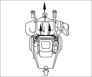
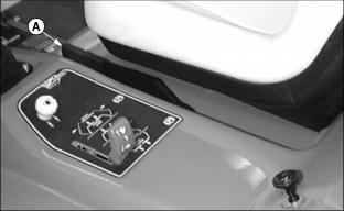
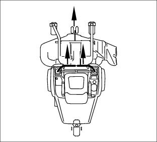
Lubricate Neutral Detent Plate Slots
IMPORTANT: Avoid damage! Lubricate detent plate slots to help maintain smooth control lever movement. |
1. Park front mower on a hard level surface.
2. Stop engine and engage park brake.
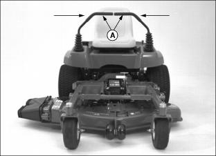
4. Move both control levers (A) inward to the centered neutral position.
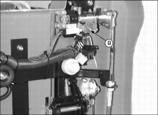
5. Raise and secure cowling in the open position.
6. Locate each control lever neutral detent plate (B) behind the front mower cowling.
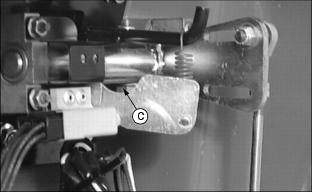
7. Lubricate each detent plate slot (C) with a small amount of grease. (See Grease in this section for the proper application.)
Checking and Aligning Control Levers
Check Alignment:
1. Park front mower on a hard level surface.
2. Stop engine and engage park brake.
3. Move both control levers (A) inward to the centered neutral position.

4. Push both control levers completely forward:
· Check control levers for equal forward and up and down alignment.
· If positions of the control levers are unequal, an adjustment is necessary.
Alignment Procedure
1. Raise and secure cowling in the open position.
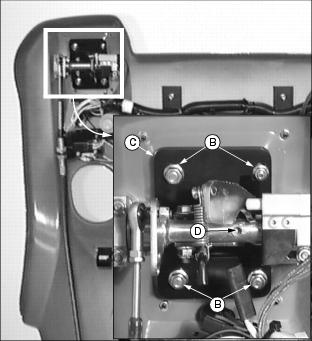
2. To adjust forward position of control levers:
· Slide control lever backplate (C) to desired position within slots.
3. Locate adjustment setscrew (D).
· To adjust position of control lever up and outward, turn setscrew clockwise.
· To adjust position of control lever down and toward each other, turn setscrew counterclockwise.
4. Lower cowling. Check adjustment.
5. Adjust tracking. (See Adjust Tracking in this section.)
Adjusting Park Brake
Test Park Brake:
1. Stop front mower on a maximum 17" slope.
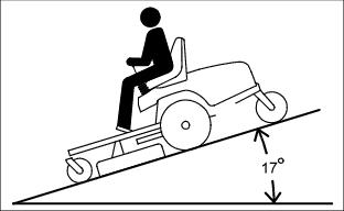
2. Raise park brake lever (A) to the (Z)position.
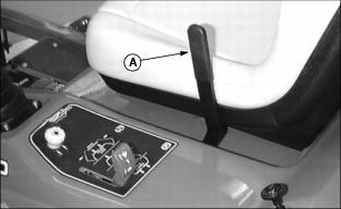
· A properly adjusted park brake must prevent the drive wheels from turning.
· If the drive wheels turn, a brake adjustment will be necessary.
Adjust Park Brake-Primary Adjustment
1. Park front mower on a hard level surface.
NOTE: Park brake lever (A) must be unlocked and released from the (Z) position prior to performing a park brake adjustment.
3. Raise and secure cowling in the open position.
4. Locate primary park brake adjustment assembly (B) behind the front mower cowling.
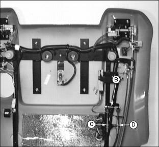
IMPORTANT: Avoid damage! Left and right wheel brake adjustments must be done evenly to accomplish satisfactory park brake performance and prevent uneven brake wear. |
· To decrease brake tension, turn bottom jam nut counterclockwise.
· To increase brake tension, turn bottom jam nut clockwise.
· Move both control levers forward.
· Drive wheels should start to turn freely and front mower should begin to travel forward.
· Brakes are adjusted too tight if an audible hydrostatic whine is detected and the front mower does not move.
8. Test and adjust brakes as necessary.
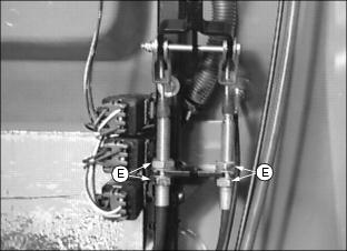
Adjust Park Brake-Secondary Adjustment
NOTE: A park brake secondary adjustment is only recommended when the primary adjustment has been completely used up.
In most instances a park brake adjustment can be accomplished with a primary adjustment. If further park brake adjustment is required:
2. Before attempting a park brake secondary adjustment:
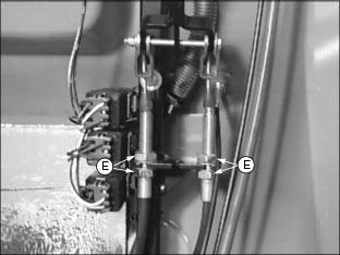
· Loosen primary adjustment jam nuts (E).
· Turn both bottom jam nuts fully to the bottom of the primary adjustment assembly.
3. Locate park brake secondary adjustment (F) on each side of the front mower.
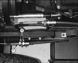
· Loosen secondary adjustment jam nuts (G).
· Turn jam nuts 6mm (1/4 in.) forward on each adjustment cable.
4. Return to the park brake primary adjustment. Make a primary adjustment and tighten jam nuts (E).
5. Test and adjust brakes as necessary.
Adjust Tracking
A proper tracking adjustment will allow the front mower to maintain a straight line direction of travel.
Right and left transmission speeds will vary with travel speed and RPM variations.
NOTE: To improve straight line tracking, drive wheel tire pressures must be equal. See Checking Tire Pressure in the Service-Miscellaneous section.
Check Tracking
3. Move both control levers inward to the centered neutral position.
4. While holding both control levers together, push both control levers forward to a desired mowing speed.
5. If the front mower travels to the right or left, an adjustment is required.
Adjust Tracking
1. Park front mower on a level surface.
2. Stop engine and engage the park brake.
4. Move both control levers inward to the centered neutral position.
5. Raise and secure cowling in the open position.
6. Loosen locknut (A) securing steering cable eyebolt (B) to the slotted control arm plate (C).
· If the front mower moves to the left, adjust right control lever.
· If the front mower moves to the right, adjust left control lever.
7. Slide cable rod end (D) inside control arm plate adjustment slot (E).
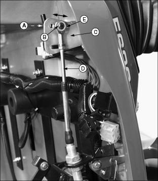
· Cable rod end should be slid forward in adjustment slot to slow down the faster transmission pump.
· Adjustments should be done in 6mm (1/4 in.) or less increments.
10. Check tracking adjustment. Continue the adjustment process until the front mower travels in a desirable straight line direction.