![]()
Introduction
Safety
Controls
Operating
Replacement Parts
Service Machine Safely
Service Interval Chart
Service Engine
Service Transmission
Service Steering and Brakes
Service Electrical
Service Miscellaneous
Troubleshooting
Storage
Assembly
Install Rear Steering Wheel Assembly
Check Machine Safety Interlock System
Specifications
Warranty
John Deere Service Literature
John Deere Quality Statement
Copyright© Deere & Company

Assembly
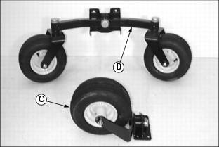
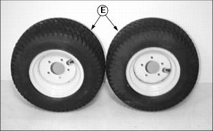
Identify Parts
C - Single Rear Steering Wheel Option
D - Dual Rear Steering Wheel Option
E - Drive Wheels (Turf Tires Shown)
Bag of Parts List
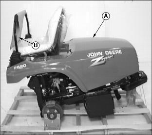
NOTE: The ZTRAK front mower is packaged and shipped from the factory without drive wheels and a rear steering wheel assembly. Customer will select rear steering wheel and drive wheel option preferences at time of purchase.
Prepare for Assembly
1. Remove front mower from the shipping crate.
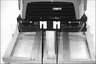
2. Cut two plastic tie straps (A) securing cowling to the front mower frame.
3. Cut steel bands securing rear of front mower to shipping crate pedestal.
Install Rear Steering Wheel Assembly
1. Lift rear of front mower with a safe lifting device.
2. Remove wood pedestal from shipping crate.
3. Check steering wheel tire inflation pressure(s).
· Keep tire(s) inflated to 110 kPa (16 psi).
NOTE: Both locknuts that attach bottom of steering wheel mounting bracket to the rear of the front mower are welded inside the frame.
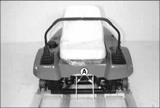
4. Install rear steering wheel assembly to front mower using four M12x30 flanged hex screws (A) and two M12 locknuts.
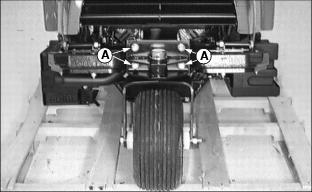
Picture Note: Top photo shows front mower equipped with a single rear steering wheel assembly.
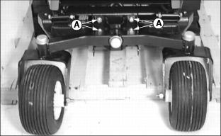
Picture Note: Bottom photo shows front mower equipped with a dual rear wheel steering wheel assembly.
Install Front Drive Wheels
1. Raise and secure cowling in the open position.(See Raising and Lowering Cowling in the Operating Machine section.)
2. Loosen (5) wheel bolts (A) stored in each drive wheel hub.
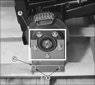
3. Remove hardware (B) securing brackets (C) to bottom of shipping crate base.
4. Lift front of machine with a safe lifting device.
5. Remove shipping crate base from under machine.
6. Remove wheel bolts and shipping brackets. Dispose of shipping brackets.
7. Check drive wheel tire inflation pressures:
· Keep tires inflated to 69 kPa (10 psi).
8. Attach one wheel to each hub using five wheel bolts, tighten until snug.
· Tighten wheel bolts in numbered sequence shown for safe wheel installation. Tighten alternately until recommended torque value is reached.
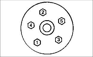
· Tighten bolts to 100 N·m (75 lb-ft.).
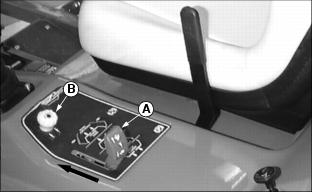
Connect the Battery
1. Raise and secure cowling in the open position.
2. Disconnect rubber hold-down strap (A).
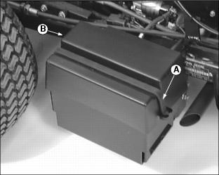
3. Remove plastic battery cover (B).
4. Connect RED positive (+) cable (B) to battery. Apply petroleum jelly or silicone spray to terminal to prevent corrosion. Make sure connection is tight. Install the red terminal cover.
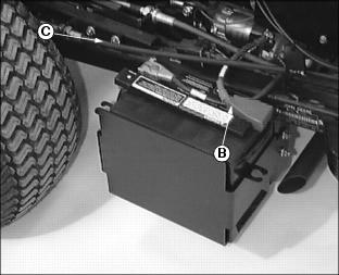
5. Connect black negative (-) cable (C) to battery. Apply petroleum jelly or silicone spray to terminal to prevent corrosion. Make sure connection is tight.
6. Check battery electrolyte level. (See Checking Battery Electrolyte Level in the Service-Electrical section.)
7. Install plastic battery cover.
Check Tire Pressure
2. Check tire pressure with an accurate gauge.
Check Engine Oil Level
1. Lift and secure cowling in the open position.
2. Remove oil dipstick (A). Wipe it clean.
4. Remove dipstick and check oil level. Oil level must be between ADD and FULL marks on dipstick.
Check Mower Deck Level
After front mower is completely assembled and the mower deck is installed, check the mower deck level.
Check the "Front to Rear" and "Side to Side" level. Refer to the Operating Mower section in the mower deck operator's manual for instruction on how to check and adjust mower deck level.
Check Machine Safety Interlock System
Perform safety system check to make sure the electronic safety interlock circuit is functioning properly. See Testing the Safety Interlock System in the Operating section.
Break-In Electric PTO Clutch
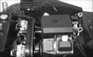
1. Start engine and push throttle lever (A) up to the full throttle (r) position.
2. With no load on mower, ENGAGE PTO switch knob (B) and allow mower to run for 10 seconds.
· DISENGAGE PTO switch knob and wait 10 seconds.