![]()
Introduction
Safety Signs
Controls
Operating Machine
Replacement Parts
Service Machine Safely
Service Interval Chart
Service Engine
Service Transmission
Service Electrical
Service Miscellaneous
Troubleshooting
Storing Machine
Assembly
Check Tire Pressure and Condition
Install Front Wheels and Tires (Heavy Duty)
Install Front Extended Mobility Technology Tires (EMT)
Install Front Lift and Tie-Down Rings
Install Fire Extinguisher and Bracket
Remove Protective Plastic From Hood And Fender Covers
Cleaning And Polishing Plastic Hood And Fenders
Specifications
Warranty
John Deere Service Literature
QUALITY DOESN'T END WHEN YOU INVEST IN A DEERE
Copyright© Deere & Company

Assembly
DO NOT Modify Machine
Do Not make any unauthorized modifications to the vehicle in any way.
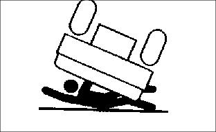
Modifications can result in making the vehicle unstable, increasing the possibility of roll-over causing severe injury or death.
Prepare For Assembly
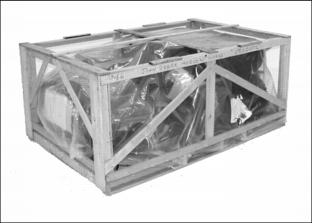
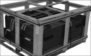
1. Remove top and sides of shipping crate.
2. Locate and identify all parts and hardware.
NOTE: The steel cargo box and front bumper brush guard are in a separate crate and has two cargo boxes to a crate.
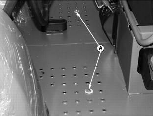
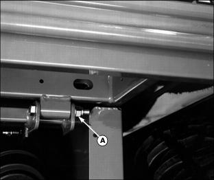
3. Remove front shipping screws and washers (A), on each side of the front platform.
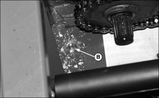
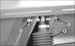
4. Remove two rear-shipping screws and washers (B), on each side of rear frame.
5. Raise vehicle using a safe lifting device. Remove pallet from under vehicle.
6. Position safety stands under vehicle.
Check Tire Pressure and Condition
1. Keep heavy-duty tires inflated to 34-41 kPa (5-6 psi) and Extended Mobility Tires (EMT) tires inflated to 27-34 kPa (4-5 psi).
2. Heavy-Duty All Purpose tire inflation pressure can be as low as 27 kPa (4 psi) and EMT tires as low as 14 kPa (2 psi) to provide a better ride.
3. Measure circumference of all tires. Tires with the largest circumference must be placed in the most rearward position to provide the most positive ground contact for drive wheels.
4. Mount wheels with valve stem to outside.
Install Front Wheels and Tires (Heavy Duty)
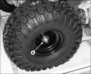
1. Install wheels using M16 x 40-flanged cap screw (A).
2. Tighten cap screws to 90 N·m (65 lb-ft.).
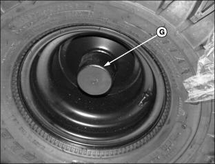
3. Install plastic hubcap (G).
Install Front Extended Mobility Technology Tires (EMT)
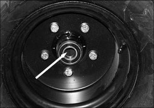
1. Install wheel and tire to axle hub on utility vehicle using one M16 x 40-flanged cap screw. Tighten to 90 N·m (65 lb-ft).
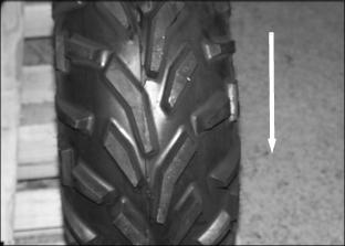
NOTE: Tire treads should be angled as shown, when viewed from the front of the vehicle. The direction of arrow is forward motion.
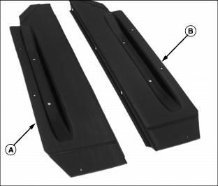
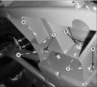
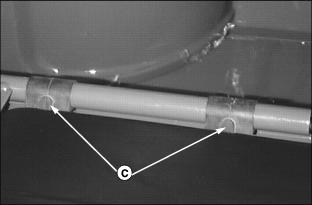
Install Belt/Chain Shields
NOTE: Before installing, identify the left and right shields (A) and (B) respectively.
It is easier to place shields on frame without rear tires and wheels installed.
1. Locate from below and place front lip of each shield (C) inside of opening (D) towards the front of frame.
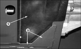
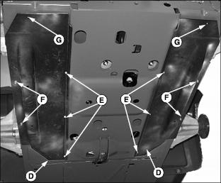
2. Use three M6 x16 self-tapping screws to attach each shield to the engine channel (E), use existing holes.
3. Use two M6 x16 self-tapping screws to attach each shield to the side frame (F), use existing holes.
4. Use one M6x20 flange head bolt and washer from the underside to attach the rear part of shield (G) to the vehicle. Use one M6 nut and washer on the inside of frame.
Install Rear Wheels and Tires
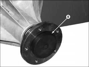
1. Install plastic cap (E) on the rear of each wheel axle shaft hub. Attach one wheel and tire to each rear axle using five wheel bolts. Tighten until snug.
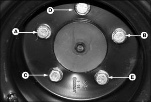
2. Tighten bolts to 90 N·m (65 lb-ft) in sequence (A), (B), (C), (D) and (E).
Lubricate Front Kingpins
NOTE: In extreme conditions, lubrication should be done every 25 hours. Under normal conditions, it should be done every 50 hours.
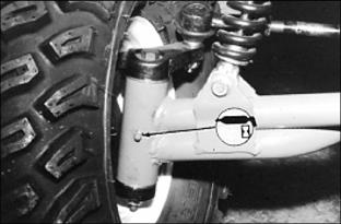
· Lubricate one grease fitting on each kingpin axle arm.
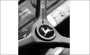
Install Steering Wheel
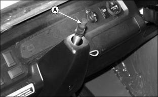
1. Remove rubber protector (A) from steering shaft.
Coat steering shaft with multi-purpose grease.
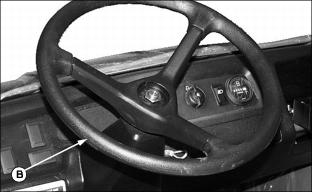
2. With front wheels straight and facing forward, install steering wheel (B).
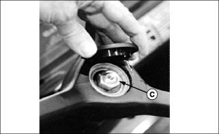
3. Install nut (C) and tighten until snug.
Power Lift Kit
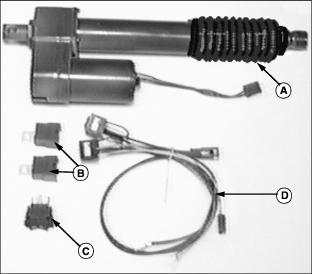
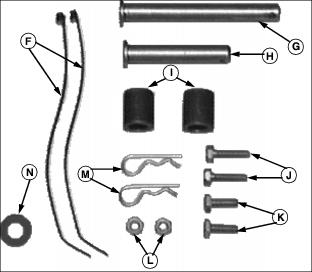
Install Power Lift Kit
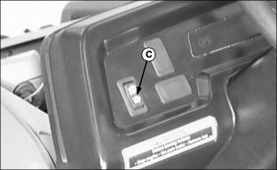
2. Push out dash plug and install the lift switch (C).
NOTE: Hold switch in place when connecting connector to avoid switch from popping out of dash.
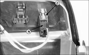
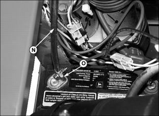
3. Plug connector (N), from main wiring harness, to switch (C).
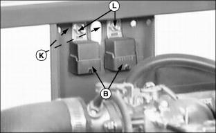
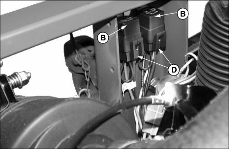
4. Install relays (B) to inside of rear frame with two cap screws (K) and nuts (L). Nuts go to inside of frame.
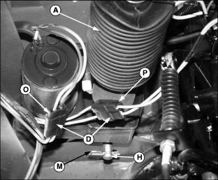
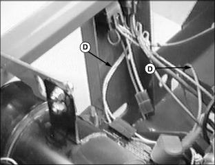
5. Connect relay wiring harness connectors (D) to relays (B), either connector to either relay.
Connect connector (P) (yellow wires) on relay harness (D) to connector on main harness (yellow wires) near thermostat.
6. Install lift cylinder (A) (motor facing to rear) with short pin (H), and spring pin (M).
7. Connect wire connector (O), from lift motor, to the relay wiring harness connector (D) (orange and black wires).
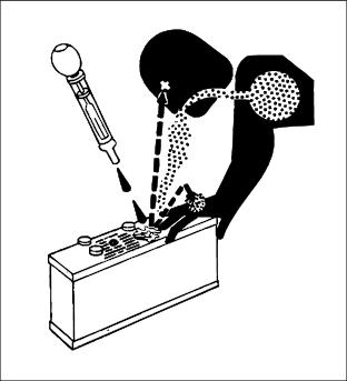
Add Electrolyte To Batteries
IMPORTANT: Avoid damage! Battery should be removed from utility vehicle before filling it with electrolyte to prevent damage to utility vehicle from spilled electrolyte. |
1. Use only battery-grade sulfuric acid electrolyte with 1.265 specific gravity.
NOTE: Some utility vehicle batteries may have shipping caps, remove and discard these caps.
2. Remove battery cell caps. (See Checking and Cleaning Battery in Electrical Service section.)
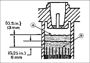
3. Slowly add electrolyte (A) until plates (B) are just covered.
4. Charge each battery at 15 amps for 10 minutes or 7 amps for 30 minutes. DO NOT exceed recommended charging rate. If electrolyte starts to boil over, decrease charging rate.
5. After charging, add electrolyte until level is 6 - 13 mm (0.25 - 0.5 in.) above plates.
Install Batteries
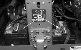
1. Install batteries in both locations (A), with the positive terminal to front left.
Picture Note: Photo MX2817 is left side battery. Photo MX2816 is the right side battery
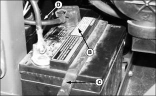
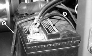
2. Install manifolds (B) with the vent tube to the front. Attach tube, route tube to the hole in frame.
3. Secure each battery with hold-down strap (C).
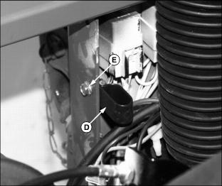
4. Install clamp (D) to inside rear frame using M6x20 bolt and M6 flange lock nut (E).
5. Use the red battery cable from the bag of parts. Attach the end of the cable with the square, and red boot (G) to the positive post of the right battery using a M6x20 bolt and M6 flange locknut. Cover the battery post connection with the square boot.
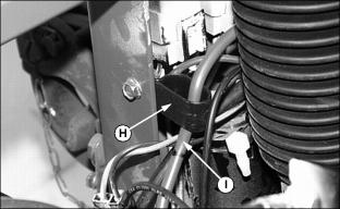
6. Slide the round boot off the other end of the cable. Route the cable (I) up through the clamp (H) on the inside rear frame, over the top of the electric lift motor, and down to near the positive post of the left battery. Install the round boot on the cable.
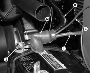
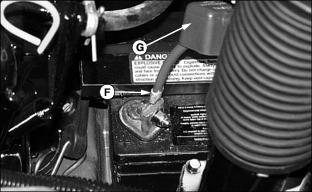
7. Insert the long red cable (K) coming from the starter and the red wire (L) from the electric lift motor into the round red boot (M).
Attach all three cables to the front left positive terminal (J) of the left battery using a M6x20 bolt and M6 locknut and washer.
8. Cover the connection with the round red boot (M). Check to be sure that the cables are routed away from the muffler and electric lift cylinder motor.
Obtain the black battery cable from the bag of parts. Attach one end of the cable (N) to the negative, rear post (O) of the right battery using a M6x20 bolt and M6 locknut and washer. Route the cable over to the rear of the electric lift motor, towards the rear, negative post of the left battery.
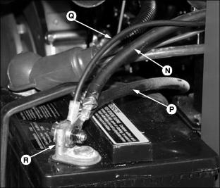
9. Attach the black (negative) cable (N) coming from the right battery, the black (negative) cable (P) coming from the engine block, and the black wire (Q) coming from the electric lift motor, to the rear, negative terminal (R) of the left battery using a M6x20 bolt and M6 locknut and washer. Check to be sure that the cables are routed away from the muffler and moving parts.
10. Tie the excess lengths of wire from the electric lift motor with tie straps, such that they are kept away from the muffler, the battery, and any moving parts.
13. Slide protective covers down over positive battery post and terminal.
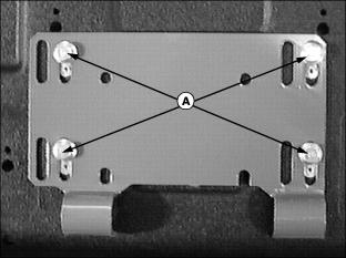
Install Hitch
1. Install four M12x35 flange bolts (A) through the hitch plate and vehicle frame, with bolt heads facing out.
2. Tighten to standard torque values the four nuts on the inside of frame.
Install Bumper Brush Guard
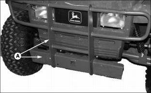
1. Fasten front bumper brush guard (A) to utility vehicle with four M12x25 carriage bolts (B) and four-flange lock nuts (C), nuts to the inside.
Install Front Lift and Tie-Down Rings
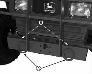
1. Install lift and tie-down ring (A) in the existing holes in the front bumper.
2. Hold ring with wooden or plastic bar to prevent rotation of the ring during tightening of the nut.
NOTE: The ring must be free to rotate. If it does not, loosen the nut until it does.
3. Tighten the 3/4 inch nut (B) until it just contacts the shoulder on the bolt.
Install Driver Seat
1. Remove hardware (A) from bottom of seat base bracket (B).
2. Position rubber seat bushings (C) onto seat frame rail with tabs facing to the rear.
3. Position seat base bracket (B) onto rubber seat bushings (C).
NOTE: The passenger seat does not use a bolt in the left rear hole.
4. Rotate seat base bracket (B) into an upward position and attach seat with hardware (A).
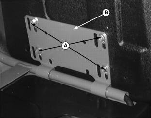
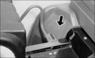
Adjust Seat
NOTE: Slots (B) allow the moving of seats forward and rearward to provide operator comfort. The passenger seat if moved to the most rearward position will contact fender (indicated by the arrow) or contact windshield (if equipped) if seat is rotated forward.
1. Loosen four cap screws (A).
NOTE: Seat can't be placed back all the way, because the back of the seat will come in contact with the front of the rear fender.
2. Move seat forward or rearward in slots (B) to position desired.
Install Cargo Box
1. Safely remove cargo box from crate.
NOTE: A hoist may be necessary to lift and align cargo box on to frame.
2. Place cargo box onto frame; align hinge tabs on rear of frame and bushings on cargo box.
3. Attach box at rear on each side using M12 x 90 cap screws and flanged lock nuts (A). Install cap screw with threads to the outside of vehicle.
NOTE: It may be necessary to tighten cap screws to squeeze tabs to minimize noise from vibration. Use spray lube to eliminate squeaks until pivot points wear in.
4. Tighten cap screws pulling in tabs until they contact ends of bushings.
5. Spray bushings and tab area with a spray lubricant.
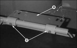
6. Attach electric lift cylinder to cargo box. Lift cargo box by hand and safely prop box open for lift cylinder access.
IMPORTANT: Avoid damage! DO NOT over extend cylinder. Rod and boot will turn, causing boot to twist. Damage to boot will occur. |
7. Turn ignition switch to RUN position ONLY. Press RAISE position on switch to extend cylinder.
8. Fasten lift cylinder (B) to cargo box with long pin (C) and spring pin (D) from the Lift Cylinder Kit.
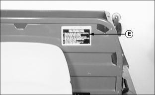
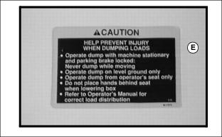
9. Apply decal (E) on front left side of load guard as shown:
· Remove backing, use squeegee to carefully smooth decal on load guard to avoid air bubbles and wrinkles. If air bubbles occur, pick with a pin and smooth out.
· Decal MUST be fully displayed and NOT obstructed by operator's seat.
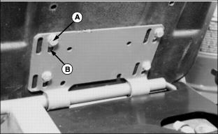
Install Fire Extinguisher and Bracket
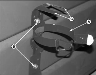
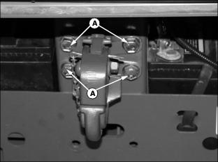
1. Place the bracket (A) against cargo box front between seats and align with already existing holes.
NOTE: Bolt heads to the outside.
2. Tighten locknuts onto the two M6x16 bolts (B).
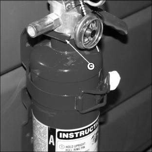
3. Place the fire extinguisher into the bracket, so that the bracket tongues (C) fit into the grooves of the extinguisher head.
4. Close clamp around extinguisher body.
Remove Protective Plastic From Hood And Fender Covers
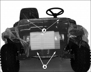
1. Remove screws (A) and lift hood up and off vehicle.
3. Using a sharp utility knife, carefully slit protective plastic where fenders join metal frame.
4. Pull plastic up and away from fender, then remove remaining plastic in joint by pulling from below.
5. Remove protective plastic from rear fenders and box extensions.
6. Replace hood, tighten top screws first then push hood upward leaving space all around headlight housings.
Cleaning And Polishing Plastic Hood And Fenders
1. Remove excess dust or dirt.
2. When surface is dry, spray on PLEDGE®* and leave on 30 to 60 seconds.
3. Using a dry soft cloth (i.e. cheesecloth) wipe off to bring out lustre.
Prepare Fuel System
1. Add diesel fuel to fuel tank.
2. Open both fuel shut-off valves:
· Arrow indicator up on the fuel tank shut-off valve.
· Lever down, pointing to "O" (open) position on fuel filter shut-off valve.
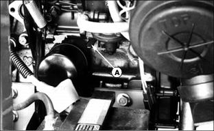
3. Move fuel pump primer lever (A) up and down. Continue operating lever until:
· Sight bowl of fuel filter is full of fuel.