![]()
Introduction
Safety Signs
Controls
Operating Machine
Replacement Parts
Service Machine Safely
Service Interval Chart
Service Engine
Engine Warranty Maintenance Statement
Prepare To Service Vehicle Safely
Changing Engine Oil and Filter
Draining, Flushing, and Filling Cooling System
Cleaning Rubber Dust Unloading Valve
Checking Air Restriction Indicator
Replacing Air Cleaner Elements
Checking Optional Spark Arrestor
Do Not Use Galvanized Containers
Checking and Cleaning Fuel Filter Sediment Bowl
Servicing Fuel Injection Nozzles
Service Transmission
Service Electrical
Service Miscellaneous
Troubleshooting
Storing Machine
Assembly
Specifications
Warranty
John Deere Service Literature
QUALITY DOESN'T END WHEN YOU INVEST IN A DEERE
Copyright© Deere & Company

Service Engine
Engine Warranty Maintenance Statement
Maintenance, repair, or replacement of the emission control devices and systems on this engine, which are being done at the customers expense, may be performed by any nonroad engine repair establishment or individual. Warranty repairs must be performed by an authorized John Deere dealer.
Avoid Fumes
· If it is necessary to run an engine in an enclosed area, use an exhaust pipe extension to remove the fumes. |

Engine Oil
Use oil viscosity based on the expected air temperature range during the period between oil changes.
The following John Deere oils are preferred:

The following John Deere oils are also recommended, based on their specified temperature range:
Other oils may be used if above John Deere oils are not available, provided they meet one of the following specifications:
· SAE 10W-40-API Service Classification SG or higher
· SAE 5W-30-API Service Classification SG or higher
· SAE 10W-30-API Service Classification SG or higher
· SAE 30-API Service Classification SC or higher
Prepare To Service Vehicle Safely
1. Stop engine and apply parking brake.

3. Perform all the following services.
Checking Engine Oil Level
NOTE: Check utility vehicle engine oil level before each use.
1. Park utility vehicle on a level surface.
2. Stop engine and engage park brake.

4. Remove dipstick (A). Wipe dipstick clean.
5. Insert dipstick fully into tube.
6. Remove dipstick. Check oil level on dipstick.
7. Oil level must be between crosshatch area on dipstick.

8. If oil level is low, add oil to bring oil level no higher than the top of crosshatch on dipstick. Remove cap in engine valve cover to add oil. (See Engine Oil in this section for correct application.)
9. If oil level is above crosshatch area, drain to proper level. Determine cause of this condition and correct.
10. Install dipstick. Lower cargo box.
Changing Engine Oil and Filter
NOTE: Severe or unusual conditions may require a more frequent service interval, as often as 25 hours.
Change engine oil and filter after first 20 hours of break-in operation. Thereafter, change engine oil and filter every 200 hours.
1. Run engine to warm the oil.
2. Park utility vehicle on a level surface.
3. Stop engine and engage park brake.
5. Place drain pan under vehicle below engine drain plug.

6. Remove drain plug (B) on rear of engine to drain oil.
7. Remove and discard oil filter (A).

8. Clean oil filter base with a clean, dry rag. Apply a film of clean engine oil on gasket of new filter.
9. Install filter. Turn filter clockwise until gasket makes contact with mounting surface. Tighten 1/2 to 3/4 turn after gasket contact.

11. Remove filler cap in top of engine. Add oil. (See Engine Oil in this section.) Approximate oil capacity is 2.0 L (2.1 qt).
12. Start engine and check for leaks.
13. Stop engine. Remove dipstick and check oil level. Oil level must be between crosshatch marks. Add oil as necessary.
Service Cooling System Safely

Cleaning Radiator Screens
The screens are located at the front and side of panel under passenger seat.

1. Clean the front screen with a rag, brush, or compressed air.

2. Remove side screen (A) which is held in place with one cap screw and washer.
3. Clean and install side screens.
4. Remove screen in front of radiator by lifting up.

5. Pull up screen (B) and clean.
Engine Coolant
The following John Deere coolant is preferred:
· PRE-DILUTED DIESEL ENGINE ANTI-FREEZE/SUMMER COOLANT (TY16036).
If preferred pre-diluted coolant is not available, the following John Deere concentrate is recommended:
· DIESEL ENGINE ANTI-FREEZE/SUMMER COOLANT CONCENTRATE (TY16034).
These coolants exceed industry specifications: ASTM D5345, D4656, D4985, D3306, and GM6038. They are designed with 5-year or 5000 hour long life formulation (subject to testing annually for conditioner level) for use in all heavy duty diesel engines. These coolants have a coolant conditioner added to help protect against liner pitting and cavitation.
If neither of the above coolants is available, use an ethylene glycol base coolant that meets the following specification
Check container label before using to be sure it has the appropriate specifications for your machine. Use coolant with conditioner or add conditioner to coolant before using.
Mix approximately 50 percent antifreeze with 50 percent distilled or deionized water. This mixture will provide freeze protection to -37 degrees C (-34 degrees F).
Certain geographical areas may require lower temperature protection. See the label on your antifreeze container or consult your John Deere dealer to obtain the latest information and recommendations.
The preferred antifreeze provides:
· Corrosion-resistant environment within the cooling system.
· Protection against liner pitting and cavitation.
· Compatibility with cooling system hose and seal material.
· Protection during cold and hot weather operations.
Engine Coolant Drain Interval
When using John Deere Pre-Diluted (TY16036) Automobile and Light Duty Engine Service coolants, drain and flush the cooling system and refill with fresh coolant mixture every 36 months or 3,000 hours of operation, whichever comes first.
When using John Deere Concentrate (TY16034) Automobile and Light Duty Engine Service coolants, drain and flush the cooling system and refill with fresh coolant mixture every 24 months or 2,000 hours of operation, whichever comes first.
If above John Deere Automobile and Light Duty Engine Service coolants are not being used; drain, flush, and refill the cooling system according to instructions found on product container or in equipment Operator's Manual or Technical Manual.
Checking Coolant Level

To check coolant level simply look at plastic overflow tank (A). It should contain approximately 25-50 mm (1-2 in.) of coolant when engine is cold.
Draining, Flushing, and Filling Cooling System
NOTE: Check condition of coolant system hoses and install new hoses when necessary.
1. Stop engine and let it cool.

3. Turn remote fill cap (A) slowly to the stop. This will release cooling system pressure.
NOTE: If radiator drain plug is seized or if it is difficult to access, remove two self-tapping screws that hold radiator in place. Raise a little to remove bottom radiator hose to drain coolant.
4. Remove remote fill cap (A).
5. Remove seat and seat base cover.

6. Remove radiator drain plug (B) and drain coolant into a container.

7. Loosen block drain (C), located to the left of dipstick, one or two turns. Drain coolant from engine block. (Drain may be BLACK in color).
8. After coolant has drained, install radiator plug (or connect bottom hose) and close block drain.
IMPORTANT: Avoid damage! To prevent engine damage, DO NOT pour water into a hot engine. DO NOT operate engine without coolant. |
9. Fill the cooling system with clean water and PT500 John Deere Cooling System Cleaner or PT592 John Deere System Quick Flush or an equivalent. Follow directions provided with product.

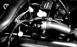
· Remove capscrews (D) to remove engine thermostat housing, thermostat and O-ring. Replace thermostat O-ring if damaged.
· Fill engine with flushing solution.
· Install O-ring, thermostat and thermostat housing. Install and tighten capscrews to 26 N·m (230 lb-in.).

· Remove plug (E) at top of radiator.
· Fill cooling system with flushing solution until solution comes from radiator plug hole. Install and tighten plug.

· Continue to fill cooling system until flushing solution level is at bottom of filler neck. Install and tighten remote fill.
10. Start and run engine until operating temperature is reached.
11. Turn remote fill cap slowly to the stop.
12. Release cooling system pressure before removing cap.
13. Remove radiator drain plug (or disconnect bottom hose) and open engine block drain quickly to drain the cooling system before rust and dirt settle.
14. Install radiator drain plug (or connect hose) and close engine block drain.
15. If necessary, remove and clean overflow tank. Install tank after cleaning.
16. Use specific coolant to fill cooling system.
· Use a solution of ethylene glycol antifreeze without a stop-leak additive and clean soft water. Chart on container will give you information on mixture rate of antifreeze-to-water solution for freeze protection in your area. (See your John Deere dealer for information on arctic operation.)
· Remove capscrews (D) to remove engine thermostat housing, thermostat and O-ring. Replace thermostat, O-ring if damaged.
· Fill engine with coolant solution.
· Install O-ring, thermostat and thermostat housing. Install and tighten capscrews to 26 N·m (230 lb-in.).

· Remove plug (E) at top of radiator.
17. Fill cooling system with coolant solution until solution comes from radiator plug hole. Install and tighten plug.

18. Continue to fill cooling system until coolant level is at bottom of filler neck. Install and tighten remote fill.
IMPORTANT: Avoid damage! If coolant temperature indicator comes ON while engine is operating, stop engine and add more coolant and water to radiator. |
19. Operate engine until cooling fan starts turning. Stop engine and allow to cool.
20. Check that coolant level is to the bottom of filler neck.
21. Fill coolant recovery tank until approximately 25-50 mm (1-2 in.) of coolant is present.
22. Replace and tighten radiator cap.
23. Check all hose clamps and tighten if necessary.
Cleaning Rubber Dust Unloading Valve
IMPORTANT: Avoid damage! Never operate engine without air cleaner element and rubber dust unloading valve installed. |

2. Squeeze lips of dust unloading valve (A) together to allow large particles of dirt to fall out. Remove from air cleaner housing and wash if greasy. Replace if damaged.
Checking Air Restriction Indicator

1. The air restriction indicator is installed on the air cleaner. When indicator is red or at 6.2 kPa (25 in. of H2O) vacuum, change primary element.
NOTE: If utility vehicle is operated in dusty environment or conditions, indicator should be checked more often.
2. Push button at the end of the indicator to reset restriction indicator, then stop engine.
Replacing Air Cleaner Elements
NOTE: An air restriction indicator is installed on air cleaner. When indicator is red or at 6.2 kPa (25 in. of H2O) vacuum, change primary element.
1. Stop engine and engage park brake.
2. Access from rear of vehicle.

3. Unlatch two spring clips (A) holding air cleaner canister cover (B) to housing. Remove cover.
IMPORTANT: Avoid damage! If utility vehicle is operated in dusty environment or conditions, element should be checked more often. |

4. Remove the primary element (C) and replace with a new one.
5. Install canister cover and engage latches.
6. Start engine and operate at a slow idle.
IMPORTANT: Avoid damage! DO NOT remove secondary air cleaner until air restriction indicator is red. This will keep contamination to the intake system at a minimum. |
7. Check air restriction indicator. If indicator rises above 2.5 kPa (10 in. of H2O), stop engine and change secondary element.
8. Remove cover and primary element.

9. Pull secondary element from filter housing. Install new secondary element.
10. Install primary filter and cover.
11. Push reset button of air restriction indicator.
12. Access from the rear of vehicle.
Check Air Intake
Check to be sure air intake tube through frame is free from obstructions.

Location is under passenger seat and indicated by arrow.
Checking Optional Spark Arrestor

Check to be sure screen deflector (A) is not plugged or deteriorated.
Spark arrestor can be removed and cleaned using compressed air.
Do Not Use Galvanized Containers
DO NOT USE a galvanized container to store diesel fuel.
Store fuel in plastic containers, aluminum containers, or specially coated containers made for diesel fuels.
DO NOT USE brass-coated containers: brass is an alloy of copper and zinc.
Checking and Cleaning Fuel Filter Sediment Bowl
NOTE: Check for water or sediment in bowl. Red ring will float when water is present.
If necessary, remove bowl for cleaning.
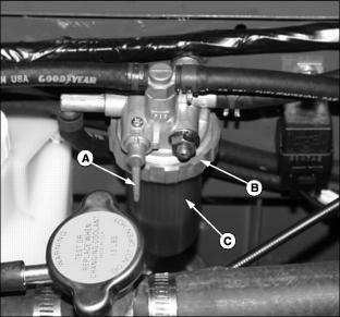
1. Turn fuel filter lever (A) up so arrow points to "C" (Closed) position.
2. Turn collar (B) to remove bowl (C).
3. Clean bowl. Install bowl and collar. (Refer to Replacing Fuel Filter in this section.)
4. Turn fuel filter lever down so arrow points to "O" (Open) position.
Replacing Fuel Filter
1. Park vehicle on a level surface and engage park brake.

3. Turn fuel filter lever (A) up so arrow points to "C" (Closed) position.
4. Turn collar (B) to remove bowl (C).
5. Pull filter from filter base.

6. Clean bowl. Make sure float ring (D), and spring (E) and O-ring (F) are in filter bowl.
7. Install new fuel filter. Install bowl and tighten collar securely.
8. Turn fuel filter lever down so arrow points to O (Open) position.
Bleeding Fuel System
DO NOT attempt to service injection pump or fuel injectors yourself. Special training and special tools are required. See your John Deere dealer.
· After you service fuel system.
1. Make sure there is fuel in fuel tank.
2. Open both fuel shut-off valves:
· Arrow indicator up on fuel tank shut-off valve.
· Lever down point to O (open) position on fuel filter shut-off valve.

3. Move fuel pump primer lever (A) up and down. Continue operating lever until:
· Sight bowl of fuel filter is full of fuel.
· You can hear fuel returning to tank through return hose.
If fuel filter has been cleaned or changed, fuel will be heard immediately returning to tank when the primer lever is operated. Continue operating lever until you can hear the return flow stop and then start again.
Servicing Fuel Injection Pump
NOTE: The fuel injection pump is calibrated by the engine manufacturer and should not require any adjustments.
IMPORTANT: Avoid damage! DO NOT clean a warm fuel injection pump with steam or water. Clear debris from under injection pump regularly. |
Changing injection pump in any way not approved by manufacturer will end warranty. See your copy of John Deere warranty on this machine.
DO NOT service injection pump. See your John Deere dealer for service.
If the engine is hard to start, lacks power, or runs rough, check the TROUBLESHOOTING section of this manual.
After performing the checks in the TROUBLESHOOTING section and your engine is still not performing correctly, contact your John Deere dealer.
Servicing Fuel Injection Nozzles
If injection nozzles are not working correctly or are dirty, engine will run poorly. See your John Deere dealer for service.