
Introduction
Product Identification
Safety
Preparing Vehicle
Installing
Removing
Operating
Replacement Parts
Service
Troubleshooting
Storage
Assembly
Identify Parts in Snowthrower Carton
Assemble Chute and Welded Frame
Specifications
Quality Statement
Copyright© Deere & Company

Assembly
Identify Parts in Snowthrower Carton
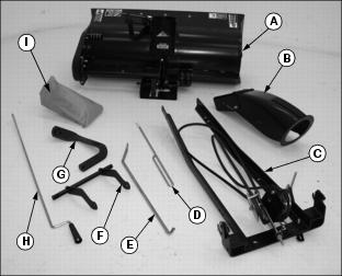
C - Welded Frame with Idlers and Belt
Bag of Parts (I) Contains:
Assemble Chute and Welded Frame
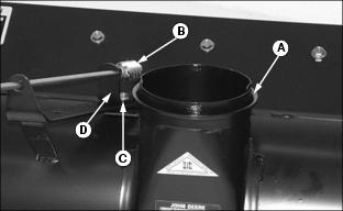
1. Apply multipurpose EP grease or an equivalent on chute base (A) and worm gear (B).
2. Loosen nut (C) and move worm gear bracket (D) away from chute base.
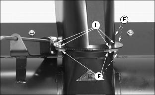
3. Fasten chute to base with three clips (E) and six M5 x 20 bolts and lock nuts (F).
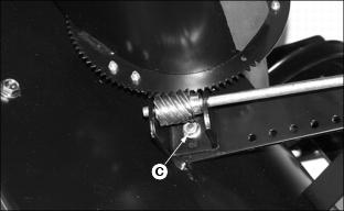
4. Move worm gear against teeth on discharge chute and tighten nut (C).
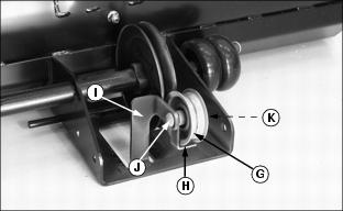
5. Install idler sheave (G) and belt guide (H) to welded support (I) using M10 x 50 bolt (J) and flange lock nut (K). DO NOT tighten at this time.
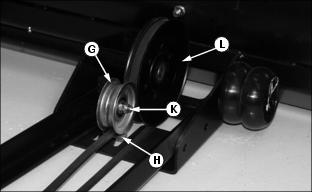
6. Slide welded frame to snowthrower and attach belt to drive sheave (L) and between idler sheave (G) and belt guide (H). Tighten nut (K).
NOTE: When tightening nuts, lift UP on opposite end of welded frame.
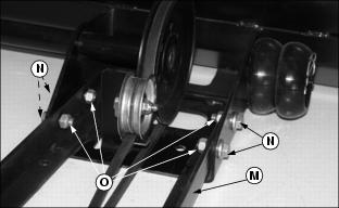
7. Lift up on welded frame (M) near sheaves and fasten to snowthrower frame with four M12 x 30 hex flange bolts (N) and M12 hex lock nuts (O), (nuts on the inside). Tighten nuts.
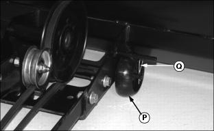
8. Install wheels (P), one on each side of snowthrower frame, and fasten with spring locking pin (Q).
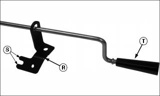
9. Slide chute control bracket (R) onto chute control rod with forked end (S) facing away from handle (T).
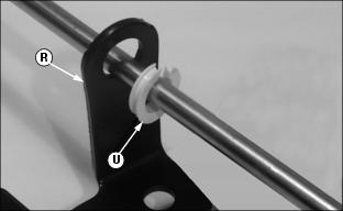
10. Position snap-in bearing on chute control rod so wider flange (U) is facing away from bracket (R) as shown. Install bearing in hole bracket (R).
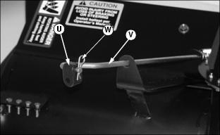
11. Install black U-joint (U) to crank support rod (V) and fasten with spring locking pin (W).
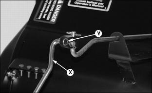
12. Insert end of chute control rod (X) into U-joint and fasten with spring locking pin (Y).
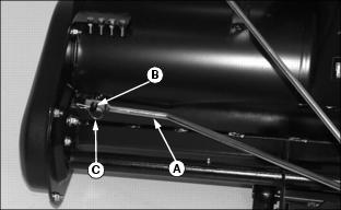
13. Install sway bar (A) on welded rod (B) and secure with large spring locking pin (C).
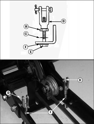
Fasten each yoke (D) to snowthrower frame with 3/8 x 41/4 in. bolt (E), .406 x 1.0 x .134 in. washer (F), retainer (G), and 3/8 in. jam nut (H) in FIRST hole (I).
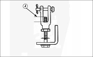
14. Adjust jam nuts until bolt exposed inside of yoke, dimension (J), is approximately 1012 mm.
Assemble Yoke to Lift Rod
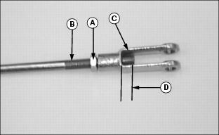
1. Turn M8 jam nut (A) onto lift rod (B).
2. Install yoke (C) on lift rod. Adjust jam nut until bolt exposed inside of yoke, dimension (D), is approximately 1012 mm.