
Introduction
Product Identification
Safety
Preparing Vehicle
Tractor Attachments Recommended
Install Pivot Bolts on Draft Arms
Install J-Bracket on Lift Lever
Installing
Removing
Operating
Replacement Parts
Service
Troubleshooting
Storage
Assembly
Specifications
Quality Statement
Copyright© Deere & Company

Preparing Vehicle
Tractor Attachments Recommended

NOTE: Before you attach snowthrower, REMOVE MOWER DECK from tractor. (See Removing and Storing Mower section in your Tractor Operator's Manual.)
· It is RECOMMENDED that the following weights be used:
-ONE 34 kg (75 lb.) Wheel Weight, one on each side. See your Authorized Service Center.
· REAR TIRE CHAINS can be added to help improve traction even more. See your Authorized Service Center.
Check Tire Pressure
NOTE: See your Tractor Operator's Manual for correct tire pressure.
Check tire pressure with an accurate gauge.
Add or remove air, if necessary.
Install Pivot Bolts on Draft Arms
NOTE: If necessary, two extra washers from Bag of Parts can be used, one on each side, to reduce side play due to welding tolerances.
1. Change hardware on both draft arms:
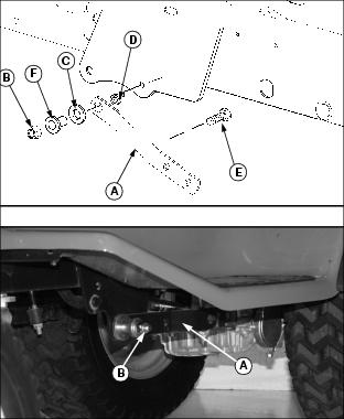
· Reuse original hardware from each draft arm (A): Flange nut (B), thick washer (C), and spacer (D).
· Discard original bolt from each draft arm and replace with M12 x 65 bolt (E) and flanged spacer (F) from bag of parts.
Install J-Bracket on Lift Lever
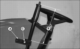
1. Install J-bracket (A) 250 mm (10 in.) from top of lever (B) with long end to the outside as shown.
2. Fasten bracket with M8 carriage bolt (C) and lock nut. Tighten nut.
Install Sway Bar Bracket
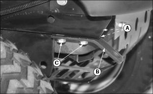
1. Slide two M8 clamp-on nuts (A) over holes on right-front side of tractor frame.
2. Align holes in sway bar bracket (B) with holes in bottom of frame and fasten with two M8 x 25 bolts (C). Tighten bolts.
3. Follow next procedure if there is only ONE hole in the tractor frame.
NOTE: If one hole in tractor frame, drill second hole (D) using sway bar bracket (B) as a template.
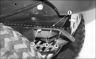
a. Install M8 clamp-on nut and M8 x 25 bolt (C) in first hole.
b. Move sway bar bracket so that it is flush with edge (E) of tractor frame. Tighten bolt (C).
c. Drill hole (D) into tractor frame using second hole of bracket as template.
d. Loosen bolt (C) and install M8 clamp-on nut and M8 x 25 bolt into drilled hole and bracket. Tighten both bolts.
Install Reflective Tape
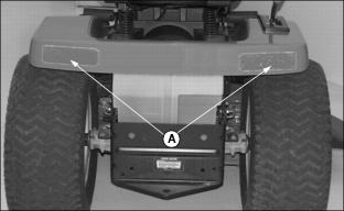
Apply reflective tape (A) to rear bumper of units without reflectors.