
Introduction
Product Identification
Safety
Preparing Vehicle
Installing
Removing
Operating
Replacement Parts
Service
Troubleshooting
Storage
Assembly
Specifications
Quality Statement
Copyright© Deere & Company

Installing
Park Vehicle Safely
· Stop vehicle on a level surface, not on a slope.
· Move vehicle in alignment with snowthrower.
· Before you leave the operator's seat, wait for engine and all moving parts to STOP.
Install Front Brackets
NOTE: RIGHT SIDE: Bracket (A) should be on the INSIDE.
LEFT SIDE: Bracket (B) should be on the OUTSIDE.
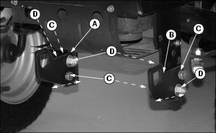
1. Fasten each bracket with two M12 hex head bolts (C) and two M12 hex flange lock nuts (D). Bolt heads should be on the INSIDE for BOTTOM bolts and on the OUTSIDE for TOP bolts.
2. Move brackets so that bottom is level with tractor frame. TIGHTEN nuts.
Install Manual Lift Assembly
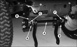
1. Slide left side of front lift shaft (A) and then right side into "D" shaped holes of front brackets (B).
2. Slide "D" shaped bearings (C) onto each front bracket.
3. Secure right side with medium spring locking pin (D).
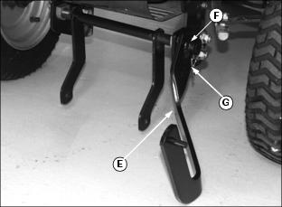
4. Install welded lift arm (E) onto left side of front lift shaft. Fasten with long drilled pin (F) and small spring locking pin (G).
Install Lift Rod
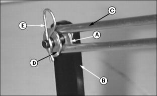
1. Slide one M10 washer (A) on end of welded lift arm (B).
2. Install lift rod (C) on welded lift arm.
3. Slide second M10 washer (D) on welded lift arm and fasten with small spring locking pin (E).
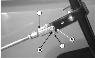
4. Attach lift rod yoke (F) to first hole of J-Bracket (G) with medium drilled pin (H) and secure with small spring locking pin (I).
Installing Snowthrower
1. Align tractor with snowthrower frame.
2. STOP engine and LOCK park brake.
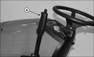
3. Pull lift lever (A) all the way back to raise front lift shaft.
4. Remove spring pin and drilled pin from C-shaped latch located on both sides of snowthrower frame and let latches swing open.
5. Slide snowthrower frame under tractor.
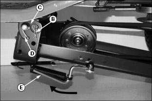
6. Remove spring locking pin (B) and C-shaped latch (C), from RIGHT side only, to allow easy installation of snowthrower frame.
NOTE: Use two extra M13x37x3 washers from Bag of Parts if C-shaped latch (C) does not pivot freely when frame is pulled to one side.
7. Attach both sides of rear snowthrower frame to draft arm pivot bolts using C-shaped latch (C). Make sure latch pivots freely.
8. Fasten C-shaped latch (C) and original spring locking pin (B) to right side.
9. Install original drilled pin (D) through hole in latch and snowthrower frame. Fasten with original spring locking pin.
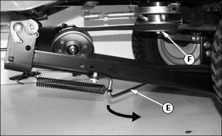
10. Pivot belt tightener lever (E) to the rear to LOOSEN belt.
11. Install belt on tractor drive sheave (F).
12. Pivot tightening lever (D) forward and lock under snowthrower frame to tighten belt.
14. Push lift lever all the way forward to LOWER front lift shaft.
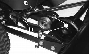
15. Fasten sway bar (G) to sway bar bracket with large spring locking pin (H).
16. Fasten two yokes (I) to front lift shaft with medium drilled pin and small spring locking pin.
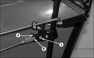
17. Install slotted end of chute control bracket (J) over drilled pin (K) and fasten bracket to J-bracket with small drilled pin and small spring locking pin (L).
NOTE: If snowthrower cannot be locked in the UP position, decrease snowthrower lift height.
18. Pull lift lever all the way back and lock snowthrower in the RAISED position.
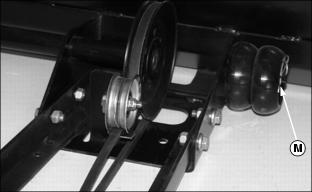
19. Move wheels to the storage position and secure with original spring locking pins (M).